


CHAPTER 2 NDA-24296
Page 118
Revision 1.0
PH-SW10
Time Division Switch
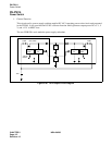
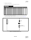
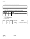
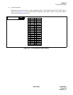
2. Mounting Location/Condition
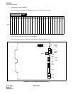
This circuit card is mounted in PIM number zero (0) of the slot shown below.
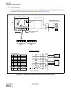
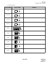
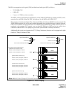
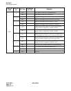
3. Face Layout of Lamps, Switches, and Connectors
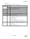
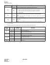
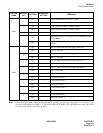
The face layout of lamps, switches and connectors is shown in Figure 2-54.
Figure 2-54 Face Layout of PH-SW10 (TSW)
00 01 02 03 04 05 06 07 08 09 10 11 12
13 14 15 16 17 18 19 20 21 22 23
Mounting Module
PIM
PIM0
TSW #1
TSW #0
1 2 3 4 5 6 7 8
SW11
TSWACT
MUXACT
PLOACT
MB
TSWMBR
PLOMB
M3SY
M2SY
M1SY
M0SY
CFT
SYNC
ICK
ECK
SW03
SW04
MUX3
MUX2
MUX1
PMCA
PMJ
PMN
SW12