


CHAPTER 2 NDA-24296
Page 132
Revision 1.0
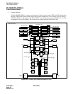
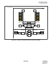
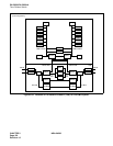
PH-SW12
Time Division Switch
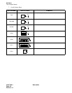
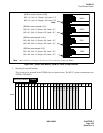
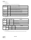
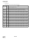
4. Lamp Indications
Lamp indications for this circuit card are shown in the table below.
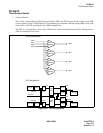
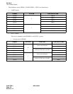
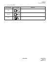
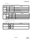
5. Switch Settings
Standard settings for switches on this circuit card are shown in the table below.
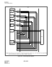
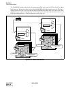
6. External Interface
See the NEAX2400 IPX Installation Manual for information about the cable connection to MUX.
LAMP NAME COLOR STATE
TSWACT
Green Remains lit while the TSW block is in ACT state.
Red Remains lit while the TSW block is in Make-busy state.
Off Remains off while the TSW block is ST-BY side.
M3SY Green Lights when MUX #3 synchronization has been established.
M2SY Green Lights when MUX#2 synchronization has been established.
M1SY Green Lights when MUX#1 synchronization has been established.
M0SY Green Lights when MUX#0 synchronization has been established.
PLO 1 Green Lights when the Frame Head signal and clock signals are received from the PLO 1.
PLO 0 Green Lights when the Frame Head signal and clock signals are received from the PLO 0.
SWITCH
NAME
SETTING
STANDARD
SETTING
MEANING
MB
UP Circuit card Make-busy.
DOWN × Circuit card Make-busy cancel.
TSWMBR
UP TSW Make-busy request.
DOWN × TSW Make-busy request cancel.
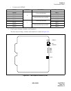
SWITCH
NAME
SWITCH
NO.
SETTING
STANDARD
SETTING
MEANING
TONE
1OFF × Fixed.
2
ON (The last byte data of the DTG ROM is “FE.”)
OFF × (The last byte data of the DTG ROM is “FF.”)