


CHAPTER 3 NDA-24296
Page 186
Revision 1.0
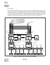
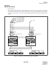
PH-CK16
Phase Lock Oscillator
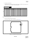
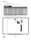
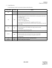
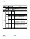
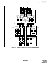
5. Switch Settings
Standard settings of switches on this circuit card are shown in the table below.
SWITCH
NAME
SETTING
STANDARD
SETTING
MEANING
MB
UP Circuit card Make-busy.
DOWN × Circuit card Make-busy cancel.
SW03 1 - F 1 Fixed to “1.”
SWITCH
NAME
SWITCH
NO.
SETTING
STANDARD
SETTING
MEANING
SW01
1
ON × Clock subordinate office.
OFF Clock source office.
2
ON Digital Clock Supply route zero (DCS 0) is used.
OFF Digital Clock Supply route zero (DCS 0) is not used.
3
ON Digital Clock Supply route one (DCS 1) is used.
OFF Digital Clock Supply route one (DCS 1) is not used.
4
ON
8 KHz of Frame Head signals are extracted from the DCS
signals (which is composed of 64 KHz + 8 KHz).
OFF
8 KHz of Frame Head signals are not extracted from the DCS
signals (which is composed of 64 KHz + 8 KHz).
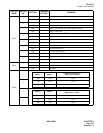
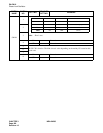
5
ON
When clock source failure has occurred in all supply routes, the
PLO outputs the original clock of the internal oscillator.
OFF
When clock source failure has not occurred in all supply routes,
the PLO continues outputting the current phase clock.
6
ON
This circuit card is associated with SYNC (PA-CK16) card and
5 m Frame Pulse (FP) is supplied by the SYNC card.
OFF This circuit card is not associated with SYNC (PA-CK16) card.
7
ON A-law CODEC is used for the hold music.
OFF × µ-law CODEC is used for the hold music.
8OFF × Not used.