


NDA-24296 CHAPTER 2
Page 113
Revision 1.0
PH-PW14
Power Switch
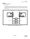
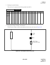
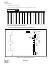
2. Mounting Location/Conditions
This circuit card is mounted in the following shaded slots (00, 01).
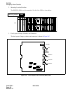
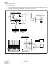
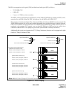
3. Face Layout of Lamps, Switches, and Connectors
The face layout of lamps, switches, and connectors for this circuit card is shown in Figure 2-50.
Figure 2-50 Face Layout of the PH-PW14 Card
00 01 02 03 04 05 06 07 08 09 10 11 12 13 14 15 16 17 18 19 20 21 22 23
Mounting Module
TSWM/ISWM
PWR SW#0
PWR SW#1
P-ON
ALM
SW
-48V in Fuse
(125V AC/DC 15A)