


CHAPTER 3 NDA-24296
Page 544
Revision 1.0
PH-M16
Line Test
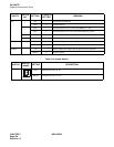
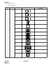
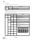
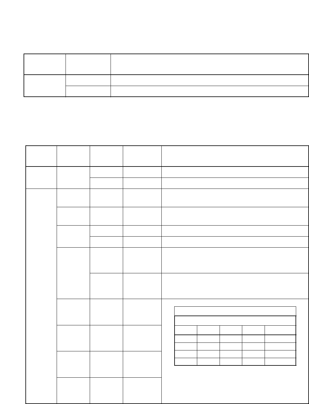
4. Lamp Indications
The table below shows lamp indications on this circuit card.
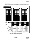
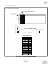
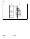
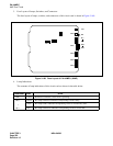
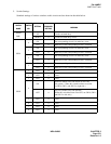
5. Switch Settings
The following is a brief description of the switches on this circuit card. When a switch has a standard
setting, it is indicated with “X” in the table below.
LAMP
NAME
COLOR DESCRIPTION
OPE/MB
Green This circuit card is operating.
Red This circuit card is make-busy.
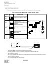
SWITCH
SWITCH
NO.
SETTING
STANDARD
SETTING
MEANING
MB
UP Circuit card make-busy.
DOWN Circuit card make-busy cancel
SW0
1ON
×
Setting of a condition of DT detection
(440Hz+350Hz)
2ON
×
Setting of a condition of RBT detection
(440Hz+480Hz)
3
ON Time of PB (DTMF) signal sending (67msc.)
OFF
×
Time of PB (DTMF) signal sending (133msec.)
4
ON
Setting of M-wire control which is concerned with sending
test tone to ODT
(Set soft control or E-wire loop back)
OFF
Setting of M-wire control which is concerned with sending
test tone to ODT
(Set soft control only)
5
6
7
8
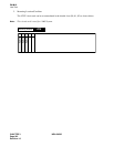
BASIC INTERVAL TIMER
SW0
5678TIME
ON OFF OFF OFF 8µ
ON ON OFF OFF 16µ
ON ON ON OFF 32µ
ON ON ON ON 64µ