


NDA-24296 CHAPTER 3
Page 233
Revision 1.0
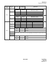
PH-CK17-A
Phase Lock Oscillator
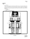
• Cable Connection Diagram
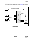
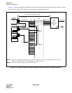
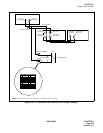
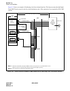
Provide the following wiring at the MDF. The connection diagram in Figure 3-30 shows an example of a
system that has the PLO cards in dual configuration.
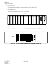
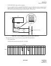
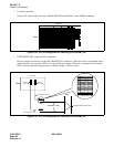
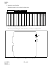
Figure 3-30 Cable Connection Diagram (ISWM) for Accepting Synchronization Clocks from an External
High-Stability Oscillator
MDF
ISW/CMG
External
High-Stability
Oscillator #1
CLK
External
High-Stability
Oscillator #0
CLK
PCM Cable(IP)
PCM Cable(IP)
DCSA
DCSB
LT Connector Cable
EXCLK1
DCSB
DCSA
LT Connector Cable
EXCLK0
EXCLK1
PLO#1
EXCLK0
PLO#0
BASEU
ISWM
maximum 400 meters (1320 feet) (24 AWG)