


CHAPTER 3 NDA-24296
Page 226
Revision 1.0
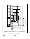
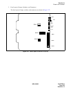
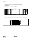
PH-CK17-A
Phase Lock Oscillator
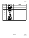
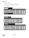
The key setting of
“
SW01
”
differs depending on the mounting location.
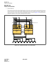
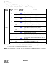
[Mounted in ISWM of IPX-U/IPX-UMG System or TSWM of 4-IMG System]
Note 1:
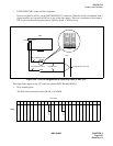
When this card is used in the 4-IMG or ISWM of IPX-U/IPX-UMG system, specify the clock source (DCS
or DTI) according to the clock network configuration for the office.
Note 2:
This standard setting is applicable when this card is mounted in ISWM of the IPX-U/IPX-UMG system.
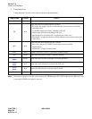
SWITCH
NAME
SWITCH
NO.
SETTING
STANDARD
SETTING
MEANING
SW01
1
ON
×
Note 2
Clock subordinate office.
OFF Clock source office.
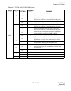
2
ON Digital Clock Supply route zero (DCS 0) is used.
OFF
×
Note 2
Digital Clock Supply route zero (DCS 0) is not used.
3
ON Digital Clock Supply route one (DCS 1) is used.
OFF
×
Note 2
Digital Clock Supply route one (DCS 1) is not used.
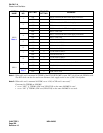
4
ON
8 KHz of Frame Head signals are extracted from the DCS
signals (which is composed of 64 KHz + 8 KHz).
OFF
×
Note 2
8 KHz of Frame Head signals are not extracted from the DCS
signals (which is composed of 64 KHz + 8 KHz).
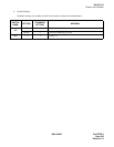
5
ON
When clock source failure has occurred in all supply routes, the
PLO outputs the original clock of the internal oscillator.
OFF
×
Note 2
When clock source failure has occurred, the PLO keeps on
outputting the current phase clock.
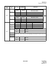
6
ON
This circuit card is used associated with SYNC (PA-CK16
WCS) card and 5 m Frame Pulse (FP) is supplied by the SYNC
card.
OFF
×
Note 2
This circuit card is not used associated with SYNC (PA-CK16
WCS) card.
7
ON A-law CODEC is used for Music-on-Hold.
OFF × µ-law CODEC is used for Music-on-Hold.
8OFF × Fixed to “OFF” (Not used).