


NDA-24296 CHAPTER 3
Page 603
Revision 1.0
PA-24DTR (DTI)
Digital Trunk Interface
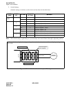
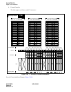
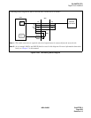
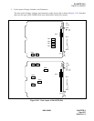
Figure 3-189 Connecting Route Diagram
TA
TB
RA
RB
POUTA
POUTB
TA
RA
RB
TB
DIU1A
DIU1B
PLO
PBX
MDF
Note 1
DTI
CARRIER
EQUIPMENT
Note 2
OUT
IN
Note 1:
This cable connection is required when clock signals must be extracted from the network side.
Note 2:
As an example, DIU1A and DIU1B leads are used in this diagram. For more information about these
leads, see Chapter 2 in this manual.
Connecting Route Diagram for the PA-24DTR (DTI) circuit card is as follows.