Chapter 2 - Installing the ViewStation EX
© Polycom, Inc. 2003 37
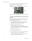
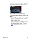
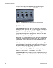
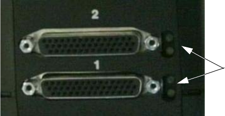
Figure 2-3 shows the network side of the network interface module
that connects to the DCE.
Figure 2-3. V.35/RS-449/RS-530 Network Interface Module (NETWORK
side)
Special Information
V.35/RS-449/RS-530 Module Interchangeability. This system only
operates with the V.35 module that is compatible with the
ViewStation FX. It is not compatible with the V.35 module that
operates with the ViewStation H.323 system. The new module uses
HD-44F connectors (ports 1 and 2), and uses a keyed RJ-45 connector
for the serial link to the back panel of the ViewStation EX system. An
HD-44M to DB-25F adapter cable is available as an option to connect
existing V.35/RS-449/RS-530 network cables, if necessary.
Cable Information. The following optional cables used to connect
the V.35/RS-449/RS-530 module to the DCE are available from the
Polycom Web store:
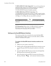
❑ V.35 “Y” cable—HD-44M to DB-25M/RS-366 and M34
“Winchester” V.35
❑ RS-449/422 “Y” cable—HD-44M to DB-25M/RS-366 and
DB-37M/RS-449/422
❑ Ascend cable—HD-44M to HD-44M
Cable drawings and pinout information is available in the “V.35
Technical Information” section of the Integrators’ Reference Manual
for ViewStation EX, ViewStation FX, and VS4000.
LEDs


