www.ti.com
PRODUCT PREVIEW
32K bytes
32K bytes
64K bytes
128K bytes
792K bytes
L2 memory
0080 0000h
008C 0000h
008E 0000h
008F 0000h
008F 8000h
0090 0000h
3/4
SRAM
4-way
cache
4-way
cache
SRAM
7/8
4-way
15/16
SRAM
4-way
SRAM
31/32
All
SRAM
000 001 010 011 111
Block base
address
L2 mode bits
cache
TMS320C6454
Fixed-PointDigitalSignalProcessor
SPRS311A–APRIL2006–REVISEDDECEMBER2006
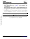
TheL2memoryconfigurationfortheC6454deviceisasfollows:
•Port0configuration:
–Memorysizeis1048KB
–Startingaddressis00800000h
–2-cyclelatency
–4×128-bitbankconfiguration
•Port1configuration:
–Memorysizeis32Kbytes(thiscorrespondstotheinternalROM)
–Startingaddressis00100000h
–1-cyclelatency
–1×256-bitbankconfiguration
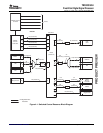
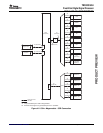
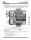
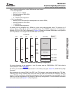
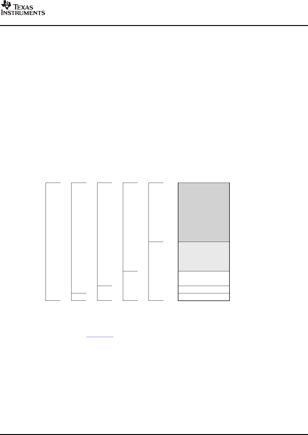
L2memorycanbeconfiguredasallSRAMoraspart4-wayset-associativecache.TheamountofL2
memorythatisconfiguredascacheiscontrolledthroughtheL2MODEfieldoftheL2Configuration
Register(L2CFG)oftheC64x+Megamodule.Figure5-4showstheavailableSRAM/cacheconfigurations
forL2.Bydefault,L2isconfiguredasallSRAMafterdevicereset.
Figure5-4.TMS320C6454L2MemoryConfigurations
FormoreinformationontheoperationL1andL2caches,seetheTMS320C64x+DSPCacheUser's
Guide(literaturenumberSPRU862).
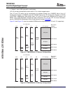
AllmemoryontheC6454hasauniquelocationinthememorymap(seeTable2-2,C6454MemoryMap
Summary).
WhenaccessingtheinternalROMoftheDSP,theCPUfrequencymustalwaysbelessthan750MHz.
Therefore,whenusingasoftwarebootmode,caremustbetakensuchthattheCPUfrequencydoesnot
exceed750MHzatanypointduringthebootsequence.Afterthebootsequencehascompleted,theCPU
frequencycanbeprogrammedtothefrequencyrequiredbytheapplication.Formoredetailedinformation
onthebootmodes,seeSection2.4,BootSequence.
SubmitDocumentationFeedbackC64x+Megamodule79


