


Disk Mirroring 291
d Click OK.
3 Shut down the system by selecting Operations > Reboot/Shutdown >
Shutdown.
4 Install the second disk drive.
a Unlock the disk tray.
b Unscrew the two retaining screws.
c Remove the disk tray.
d Connect the IDE disk cable to the disk drive.
e Connect the power harness to the disk drive.
f Fasten the new disk to the disk tray using your Phillips screwdriver and
the screws provided with the disk.
g Reinsert the disk tray.
h Screw in the two retaining screws and lock the disk tray in place.
5 Restart the system.
6 Verify that the disks begin the mirroring process.
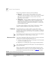
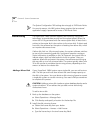
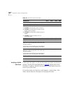
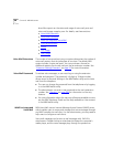
On the Call Processor front panel, check the four LEDs under the PWR
and S1 labels. The LEDs labeled 1, 2, and 3 (Figure 19
) indicate disk
status.
Figure 19 Disk and Power LEDs
Table 59 describes the possible states of the LEDs.
Table 59 Disk LED States
Explanation LED 1 LED 2 LED 3 PWR
Attempting to boot from disk 0 (zero) Off On Off On
Attempting to boot from disk 1 Off Off On On
1
2
3
S
1
P
W
R