1-8
Cisco ONS 15310-CL and Cisco ONS 15310-MA Troubleshooting Guide, R7.0
Chapter 1 General Troubleshooting
1.2.3 Perform a Terminal Loopback on a Destination-Node Port
Test the Hairpin Circuit
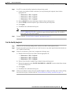
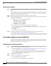
Step 1 If the test set is not already sending traffic, send test-set traffic on the loopback circuit.
Step 2 Examine the test traffic received by the test set. Look for errors or any other signal information that the
test set is capable of indicating.
Step 3 If the test set indicates a good circuit, no further testing is necessary with the hairpin loopback circuit.
Clear the hairpin circuit:
a. Click the Circuits tab.
b. Choose the hairpin circuit being tested.
c. Click Delete.
d. Click Yes in the Delete Circuits dialog box.
e. Confirm that the hairpin circuit is deleted from the Circuits tab list.
Step 4 If the test set indicates a faulty circuit, there might be a problem with the port. Continue with the
“1.2.3 Perform a Terminal Loopback on a Destination-Node Port” procedure on page 1-8.
1.2.3 Perform a Terminal Loopback on a Destination-Node Port
The terminal loopback test is performed on the node destination port in the circuit. First, create a
bidirectional circuit that originates on the source node electrical port (such as DS-1, DS-3, or EC-1) and
terminates on the destination-node electrical port. Then continue with the terminal loopback test.
Completing a successful terminal loopback to a destination-node port verifies that the circuit is good up
to the destination port.
Caution Performing a loopback on an in-service circuit is service-affecting.
Create the Terminal Loopback on a Destination-Node Port
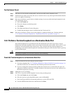
Step 1 Connect an electrical test set to the port you are testing:
a. If you just completed the “1.2.2 Perform a Hairpin on a Source-Node Port” procedure on page 1-6,
leave the electrical test set connected to the electrical port in the source node.
b. If you are starting the current procedure without the electrical test set connected to the port, use
appropriate cabling to attach the Tx and Rx terminals of the electrical test set to the connectors for
the electrical port you are testing.
Step 2 Adjust the test set accordingly.
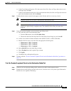
Step 3 Use CTC to set up the terminal loopback circuit on the port being tested:
a. Click the Circuits tab and click Create.
b. Give the circuit an easily identifiable name, such as DSNtoDSN.
c. Set circuit Type and Size to the normal preferences, such as STS and STS1.
d. Leave the Bidirectional check box checked and click Next.


