


1-31
Cisco ONS 15310-CL and Cisco ONS 15310-MA Troubleshooting Guide, R7.0
Chapter 1 General Troubleshooting
1.6.2 Perform a Terminal Loopback on a Source-Node Ethernet Port
1.6.2 Perform a Terminal Loopback on a Source-Node Ethernet Port
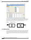
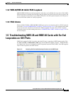
The terminal loopback test is performed on the node source Ethernet port. To do this, you create a
bidirectional circuit that starts on the node destination CE100T-8 port and loops back on node source
CE100T-8 port. You then proceed with the terminal loopback test. Completing a successful terminal
loopback to a node source port verifies that the circuit is good to the source port.
Note Terminal loopbacks require on-site personnel.
Caution Performing a loopback on an in-service circuit is service-affecting.
Complete the “Create the Terminal Loopback on a Source-Node Ethernet Port” procedure on page 1-31.
Create the Terminal Loopback on a Source-Node Ethernet Port
Step 1 Connect a test set to the port you are testing:
Note For specific procedures to connect, set up, and use the test set equipment, consult the
manufacturer.
a. If you just completed the “1.6.1 Perform a Facility Loopback on a Source-Node Ethernet Port”
procedure on page 1-29, leave the test set hooked up to the Ethernet port in the source node.
b. If you are starting the current procedure without the test set hooked up to the source port, use
appropriate cabling to attach the Tx and Rx terminals of the test set to the port you are testing. Both
Tx and Rx connect to the same port.
Step 2 Adjust the test set accordingly. (Refer to manufacturer instructions for test-set use.)
Step 3 Use CTC to set up the terminal loopback on the test port:
a. In node view, click the Circuits tab and click Create.
b. In the Circuit Creation dialog box, choose the type, such as STS, and number, such as 1.
c. Click Next.
d. In the next Circuit Creation dialog box, give the circuit an easily identifiable name such as
C1C1toC1C2.
e. Leave the Bidirectional check box checked.
f. Click Next.
g. In the Circuit Creation source dialog box, select the same Node, card Slot, Port, and STS (or VT)
where the test set is connected.
h. Click Next.
i. In the Circuit Creation destination dialog box, use the same Node, card Slot, Port, and STS (or VT)
used for the source dialog box.
j. Click Next.
k. In the Circuit Creation circuit routing preferences dialog box, leave all defaults. Click Finish.