


1-22
Cisco ONS 15310-CL and Cisco ONS 15310-MA Troubleshooting Guide, R7.0
Chapter 1 General Troubleshooting
1.3.6 Perform a Facility Loopback on a Destination-Node OC-N Port
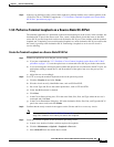
e. Click Apply.
f. Click Yes in the confirmation dialog box.
Step 4 Clear the terminal loopback circuit:
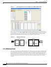
a. Click the Circuits tab.
b. Choose the loopback circuit being tested.
c. Click Delete.
d. Click Yes in the Delete Circuits dialog box.
Step 5 If the test set indicates a faulty circuit, the problem might be a faulty controller card (15310-CL-CTX or
CTX2500). Continue with the “1.3.6 Perform a Facility Loopback on a Destination-Node OC-N Port”
procedure on page 1-22.
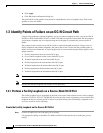
1.3.6 Perform a Facility Loopback on a Destination-Node OC-N Port
The final facility loopback test is performed on the source OC-N port in the destination node.
Completing a successful facility loopback on this port isolates the OC-N port as a possible failure point.
Caution Performing a loopback on an in-service circuit is service-affecting.
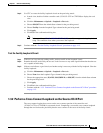
Create the Facility Loopback on a Destination-Node OC-N Port
Step 1 Connect an optical test set to the port you are testing:
a. If you just completed the “1.3.5 Perform a Terminal Loopback on an Intermediate-Node OC-N
Port” procedure on page 1-20, leave the optical test set connected to the OC-N port in the source
node.
b. If you are starting the current procedure without the optical test set connected to the OC-N port, use
appropriate cabling to attach the Tx and Rx terminals of the optical test set to the port you are
testing.
c. Adjust the test set accordingly.
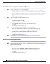
Step 2 Use CTC to set up the facility loopback circuit on the port being tested:
a. Click the Circuits tab and click Create.
b. Give the circuit an easily identifiable name, such as OCN1toOCN5.
c. Set circuit Type and Size to the normal preferences, such as STS and STS1.
d. Leave the Bidirectional check box checked and click Next.
e. In the Circuit Source dialog box, fill in the source Node, Slot, Port, and Type where the test set is
connected and click Next.
f. In the Circuit Destination dialog box, fill in the destination Node, Slot, Port, and Type (the OC-N
port in the destination node) and click Finish.
Step 3 Confirm that the newly created circuit appears on the Circuits tab list as a two-way circuit.