10006024-04 Katana
®
752i User’s Manual
12-1
Section 12
Hot Swap
The Katana
®
752i baseboard incorporates a Linear Technologies LTC1643L Hot Swap
™
con-
troller device and is fully compliant with the CompactPCI (cPCI) Hot Swap Specification (see
references in
Table 1-2). Katana
®
752i circuit boards allow for High Availability Hot Swap sys-
tems, including cPCI/PSB systems (without a cPCI interface). Some basic Hot Swap features
include:
• Ejector switch indication and Hot Swap LED control
• Back-end voltage isolation using the BD_SEL* signal and power supply health indication
using the CPCI_HEALTHY* signal
• Minimal capacitive loading on power supplies and I/O pins, according to the Hot Swap
Specification
• In-rush current limiting
HOT SWAP LOGIC (HSL) PLD
The Katana
®
752i utilizes a programmable logic device, called the Hot Swap Logic (HSL)
PLD to store various registers that provide status and affect the operation of the board.
These registers are listed below.
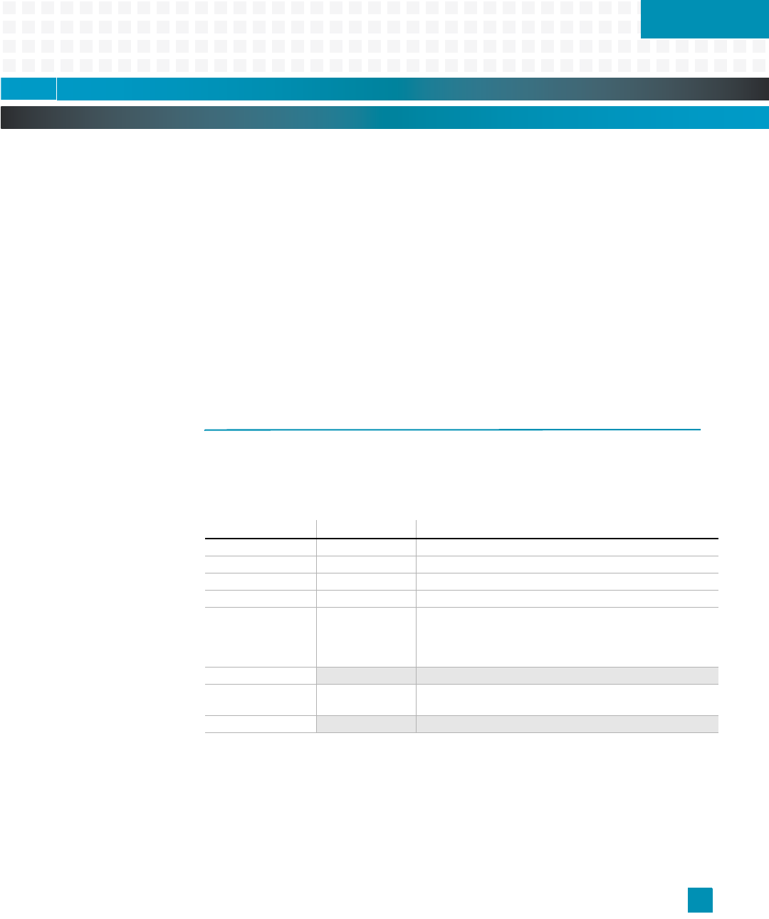
Table 12-1: HSL PLD Register Summary
Address (Hex): Name: Description:
F821,0000 J4SGA Shelf Enumeration Bus pin status from J4 conn. (read only)
F821,0001 J4GA Geographical Address from J4 connector (read only)
F821,0002 J2GA Geographical Address from J2 connector (read only)
F821,0003 CT Clk Control CT clock control registers (see page 13-3)
F821,0004 cPCI Status Bit 0, CT_EN signal: 0 = present, 1 = not present
Bit 1, cPCI present on backplane: 1 = yes, 0 = no
Bit 2, HSL_CPCI_N signal: 0 = cPCI, 1 = no cPCI
(remaining bits are zero, only used when cPCI is enabled)
F821,0005
– reserved
F821,0006 HS LED Bit 0, Hot Swap LED control: 1 = LED on; 0 = LED off
(only used when cPCI is disabled)
F821,0007
– reserved for HSL PLD version


