


10006024-04 Katana
®
752i User’s Manual
2-1
Section 2
Setup
This chapter describes the physical layout of the boards, the setup process, and how to
check for proper operation once the boards have been installed. This chapter also includes
troubleshooting, service, and warranty information.
ELECTROSTATIC DISCHARGE
Before you begin the setup process, please remember that electrostatic discharge (ESD)
can easily damage the components on the Katana
®
752i hardware. Electronic devices,
especially those with programmable parts, are susceptible to ESD, which can result in oper-
ational failure. Unless you ground yourself properly, static charges can accumulate in your
body and cause ESD damage when you touch the board.
Caution: Use proper static protection and handle Katana
®
752i boards only when absolutely
necessary. Always wear a wriststrap to ground your body before touching a board. Keep
your body grounded while handling the board. Hold the board by its edges–do not touch
any components or circuits. When the board is not in an enclosure, store it in a static-
shielding bag.
To ground yourself, wear a grounding wriststrap. Simply placing the board on top of a
static-shielding bag does not provide any protection–place it on a grounded dissipative
mat. Do not place the board on metal or other conductive surfaces.
KATANA
®
752I CIRCUIT BOARD
The Katana
®
752i circuit board is a 6U CompactPCI card assembly. It uses a 14-layer printed
circuit board with the following dimensions.
Table 2-1: Circuit Board Dimensions
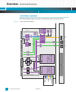
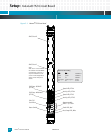
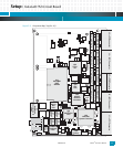
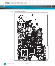
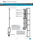
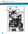
The figures on the following pages show the front panel, component maps, and jumper
locations for the Katana
®
752i circuit board.
Width: Depth: Height:
9.19 in. (233.35 mm) 6.30 in. (160 mm) < 0.8 in. (< 20.32 mm)
!