Reset Logic: Reset Sources
10006024-04 Katana
®
752i User’s Manual
3-3
RESET SOURCES
The Katana
®
752i circuit board can be reset from the following sources:
• Power-On Reset (POR) circuitry
•CompactPCI Reset
• Power Monitor Reset
• 750GL Processor Reset (JTAG header)
• Remote IPMI Reset
•Front Panel Reset
• Watchdog Timer Reset
CompactPCI Reset Enable
The Katana
®
752i has an optional configuration jumper at JP2 (see Fig. 2-4). When installed
(default condition), this jumper enables the board to send a reset signal (when the front
panel reset switch is pressed) to the cPCI system controller via the cPCI_PRST pin. Upon
receiving this signal, the cPCI system controller generates a cPCI reset. When the jumper is
not installed, the Katana
®
752i does not send the reset signal to the cPCI system controller
when the reset switch is pressed.
Another optional configuration jumper at JP1 (see
Fig. 2-4), when installed (default condi-
tion), enables the cPCI reset signal to drive a local PCI reset to the 750GL reset logic (see
Fig. 3-2). When the jumper is not installed, the Katana
®
752i ignores the cPCI reset signal.
Power Monitor
The Katana
®
752i has a power monitor circuit that detects low voltage conditions on any of
the power supply sources. The circuit will hold the oscillators off and drive the power-on
reset (POR) for as long as the low voltage condition exists.
750GL Processor Reset
The Device Bus PLD (see Chapter ) on the Katana
®
752i implements the 750GL processor
reset logic.
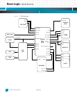
Fig. 3-2 shows how the reset signals connect to the related devices.
Note: The Device Bus PLD is also known as the MVC PLD.


