


Overview: Components and Features
Katana®752i User’s Manual 10006024-04
1-2
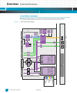
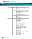
SDRAM: The Katana®752i allows for a 72-bit Small-Outline Dual In-Line Memory Module (SO-
DIMM) of up to two gigabytes to support the CPU. (Please contact Emerson for the avail-
ability of one- and two-gigabyte SO-DIMMs.) This SDRAM operates at a speed of up to 200
MHz and has Error Checking and Correction (ECC) code.
Flash: The Katana®752i supports up to 128 megabytes soldered user Flash memory for the CPU.
The Flash bank is 32 bits wide, using two or four 16-bit wide devices. The Katana®752i also
supports 512 kilobytes of socketed Flash. The Flash memory conforms to the Intel
StrataFlash
™
architecture. The CPU is capable of booting from either Flash memory.
H.110: The Katana®752i has an optional configuration that supports the H.110 Computer Tele-
phony (CT) bus in accordance with the PICMG 2.5 Computer Telephony Specification and
ECTF H.110 Specification, and it complies with Configuration 2 of the PICMG 2.15 PCI Tele-
com Mezzanine/Carrier Card Specification. The optional Agere Systems T8110 Time Slot
Interchanger (TSI) serves as a bridge between the H.110 and local CT bus.
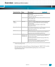
Ethernet Ports: The Katana®752i provides four, 10/100/1000BaseT, Gigabit Media-Independent Interface
(GMII) Ethernet ports (three from the MV64460 system controller, one from the 82544EI
Ethernet controller). Two ports route to the front panel RJ45 connectors, and two ports
route to the J3 CompactPCI (cPCI) connector for use either by a rear transition module or a
cPCI packet-switched backplane (cPSB). Four PHY devices (three Broadcom BCM5461S,
one Intel 82544EI) provide the physical interface for these ports. Optionally, the
Katana®752i can support two Reduced Media-Independent (RMII) 10/100BaseT Ethernet
ports routed from the PTMC sites to connector J5. Two Micrel KS8721CL PHYs support
these ports.
Serial I/O: The MV64460 system controllers provides an asynchronous console serial port, which sup-
ports EIA-232 signal levels. This serial port is accessible via a mini-DB9 connector on the
Katana®752i front panel and the backplane connector J5.
CT Bus Clocks: Optionally, the Katana®752i can provide computer telephony (CT) bus clocking. One
option supports only the CT clocks (C8A, C8B, FRAMEA, FRAMEB, NETREF1, and NETFER2)
between J4 and the PTMC sites. A second option supports CT bus clocking plus CT data traf-
fic via an Agere Systems T8110 Time Slot Interchanger (TSI). This routes H.110 to the back-
plane connector J4.