Hot Swap: Hot Swap LED and Ejector Switch Control
Katana
®
752i User’s Manual 10006024-04
12-4
Non-cPCI Hot Swap
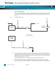
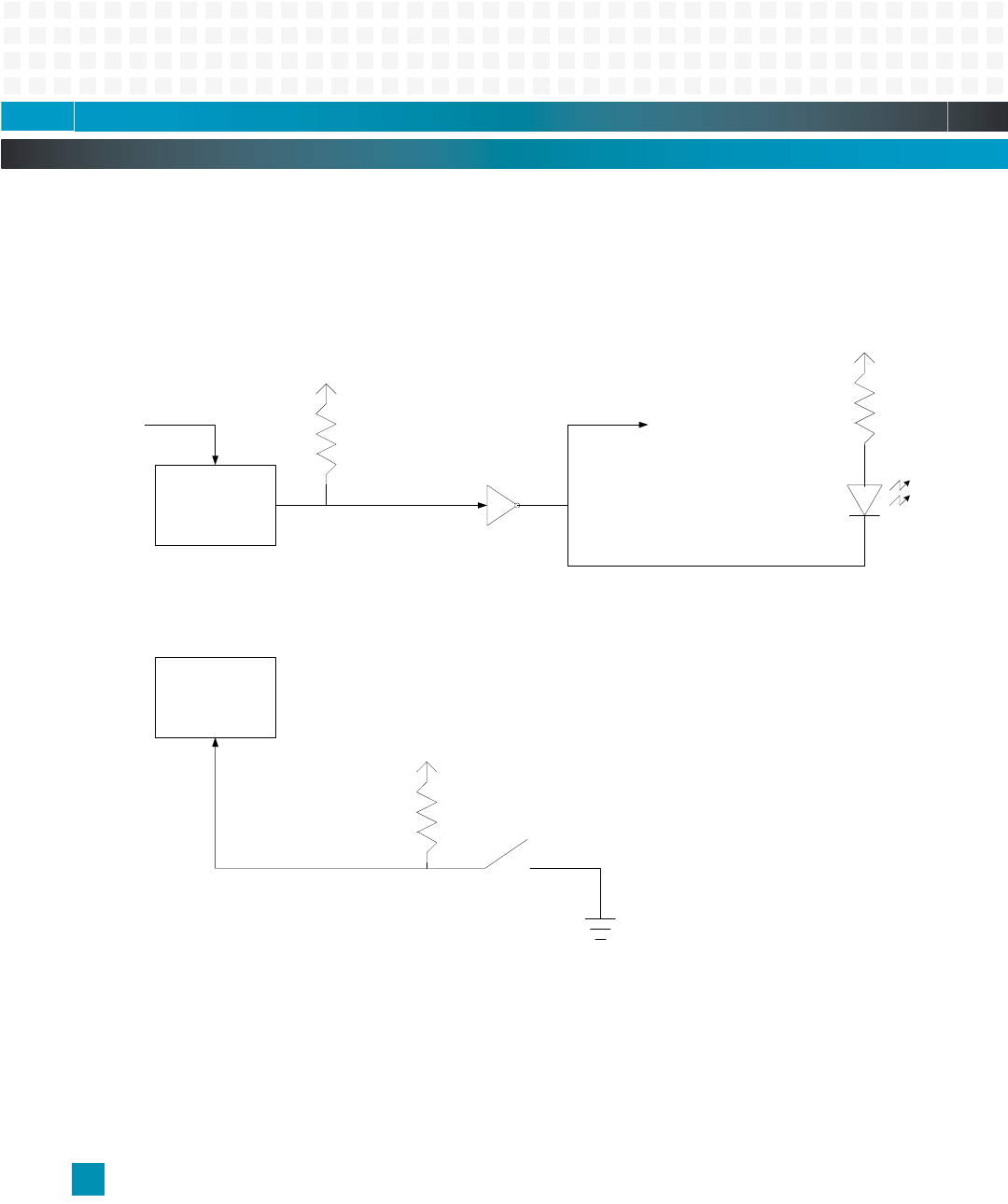
When the cPCI functionality is disabled, the LED/ejector switch control mechanism works in
conjunction with the Power Good indication from the Hot Swap controller circuit, as shown
in
Fig. 12-1.
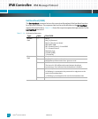
Figure 12-1: Hot Swap Controller Circuit
Note: The status of the ejector handle latch can be determined by reading the PCI0_HS bit in the MV64460 HS_CTL
register (PCI0_HS bit high = locked, PCI_HS bit low = unlocked). The status also can be read via MV644460
MPP/GPIO pin #31. It is an interruptable pin that can detect a change in the Hot Swap status, eliminating the
need for polling at the MPP pin or PCI0_HS bit.
The Hot Swap logic functions as follows when a board is inserted into a slot:
1 The Hot Swap LED illuminates immediately when the board is inserted. This is enabled
when the power good indicator, PWRGD*, from the Hot Swap controller is not being driven
3.3_EARLY
HS Controller
Marvell
MV64460
3.3_EARLY
PWRGD*
PCI0_HS
3_3V
NOTE: Discrete logic
contained inside HSL PLD
Blue Hot
Swap LED
Ejector Switch
to backplane
Healthy*
BDSEL*


