


Ethernet Interfaces: Ethernet Ports
Katana
®
752i User’s Manual 10006024-04
10-2
001 = CPSB_1 (MAC address #2)
010 = CPSB_2
011 = FRNT_1 (ETH3)
100 = FRNT_2 (ETH4)
101 = reserved
110 = reserved
111 = reserved
So for example, if the Katana
®
752i serial number is 1234, the CPSB_2 MAC address is:
00:80:F9:6C:07:52.
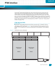
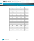
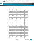
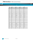
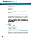
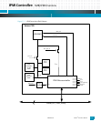
ETHERNET PORTS
The MV64460 system controller (see Chapter ) provides three 10/100/1000BaseT gigabit
Ethernet (GbE) ports. Also, the Katana
®
752i provides direct access to a fourth GbE port
from the local PCI bus via an Intel 82544EI Ethernet controller device. Two ports connect to
the front panel (see Section for pinouts), and two connect to the J3 cPSB connector (see
Table 14-3 for pinouts).
• If the Katana
®
752i is installed in a system that supports a cPSB backplane, the two ports at
J3 allow for cPSB functionality. If the Katana
®
752i is installed in a system that does not
support a cPSB backplane, the J3 ports can be routed via a rear transition module to provide
two GbE input/output ports.
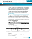
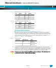
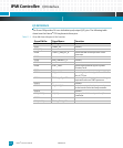
Four Broadcom BCM5461S transceivers provide the physical interface for these ports.
There are eight LEDs associated with the GbE ports (see the component map on page 2-6
for LED locations).
Table 10-1: GbE Port LEDs
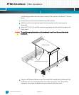
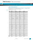
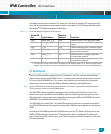
FRONT PANEL ETHERNET CONNECTOR PINOUTS
The Katana
®
752i has a dual-RJ45 connector, P1, for the two front panel Ethernet ports.
(Refer to the front panel drawing on page 2-2.) The ETH4 port connects to the 82544EI
Ethernet controller. The ETH3 port connects to the MV64460 system controller. The dual-
RJ45 connector has integrated speed (SP) and activity (ACT) LEDs to show the status of each
port. The pin assignments are as follows.
GbE Port 1 GbE Port 2
CR34=ACT CR20=ACT
CR32=LINK CR21=LINK
CR33=LINK2 CR22=LINK2
CR35=LINK1 CR23=LINK1