


Setup: Katana®752i Circuit Board
10006024-04 Katana
®
752i User’s Manual
2-7
Identification Numbers
Before you install the Katana
®
752i circuit board in a system, you should record the follow-
ing information:
❐ The board serial number:____________________________________________ .
The board serial number appears on a bar code sticker located on the back of the board.
❐ The board product identification: _____________________________________ .
This sticker is located near the board serial number.
❐ The monitor version: _______________________________________________ .
The version number of the monitor is on the monitor start-up display.
❐ The operating system version and part number: _________________________ .
This information is labeled on the master media supplied by Emerson or another vendor.
❐ Any custom or user ROM installed, including version and serial number:
________________________________________________________________ .
It is useful to have these numbers available if you need to contact Technical Support at
Emerson Network Power, Embedded Computing.
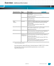
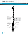
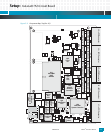
Connectors
The Katana
®
752i circuit board has various connectors, summarized as follows:
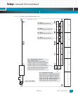
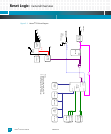
P1: P1 is a dual-RJ45 connector that provides front panel access to two 10/100/1000BaseT
Ethernet ports (see
Fig. 2-1). One port routes to the MV64460 system controller. The other
routes to the 82544EI Ethernet controller on the local PCI bus. The connector also has inte-
grated link, speed, and activity LEDs for each port. See Chapter for pinouts.
P2: P2 is a 9-pin Micro D connector on the front panel that provides EIA-232 console port access
for the 750GL processor. See
Table 5-4 for pinouts.
P3: P3 is a 16-pin header on the circuit board for the 750GL COP/JTAG interface. See
Table 4-6
for pinouts.
J1: J1 is a 110-pin connector that routes power supply signals, various CompactPCI (cPCI) util-
ity signals and Intelligent Platform Management Interface (IPMI) control signals to and from
the CompactPCI backplane. See Chapter for pinouts.
J2: J2 is a 110-pin connector that routes Geographical Address (GA) signals and power supply
signals from the CompactPCI backplane. See Chapter for pinouts.
J3: J3 is a 95-pin connector that routes the gigabit Ethernet signals to and from the Compact-
PCI packet-switched backplane (cPSB) or rear transition module. It also routes user
input/output signals directly from the J14 connector at PTMC expansion site #1. See
Chapter for pinouts.