


System Controller: Console Serial Port
10006024-04 Katana
®
752i User’s Manual
5-11
CONSOLE SERIAL PORT
The processor complex on the Katana
®
752i has an asynchronous console serial port on the
front panel. This port operates at EIA-232 signal levels, but does not provide any handshak-
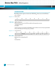
ing functionality. The connector for the front panel console port is a mini-DB9 connector,
with the following pin assignments.
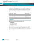
Table 5-4: Serial Console Port Pin Assignments, (P2)
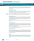
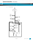
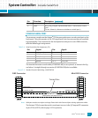
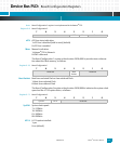
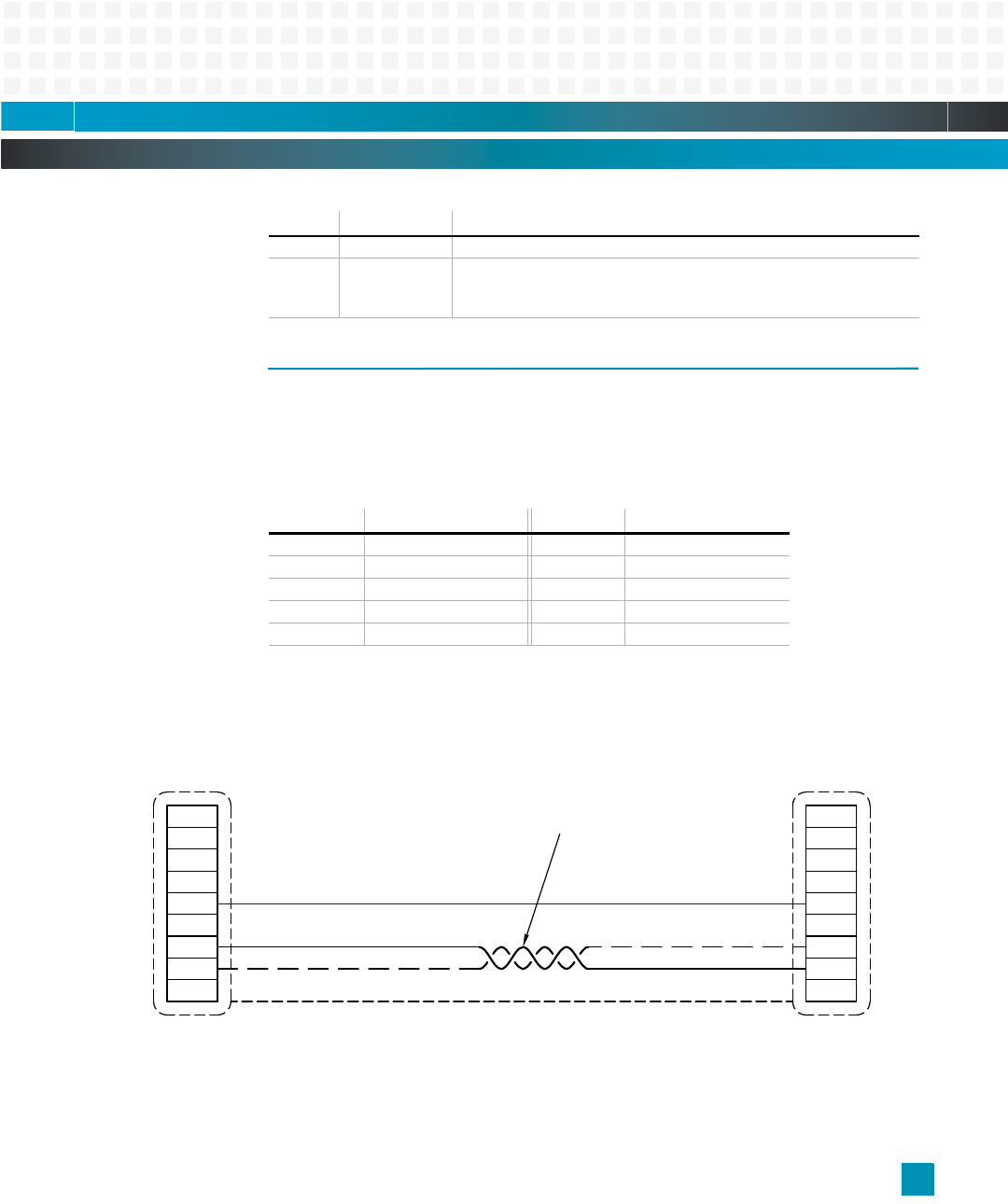
The standard Emerson console cable (#10007665-00) is cross-pinned, as shown in the fig-
ure below. A straight-through connector (#10007664-00) also is available.
Figure 5-3: Standard Console Cable Wiring, #10007665-00
Note: Cable part numbers are subject to change. Please check with Emerson before ordering replacement cables.
The Katana
®
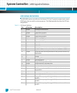
752i also provides serial console port access via the J5 CompactPCI connector
at pins E15 and D15 (refer to page 14-3 for pinouts).
30 – unused
31 input MVL_PCI0_HS signal, ejector handle status; 1=latch closed, 0=latch
open
(For rev. 0 boards, software must debounce switch input.)
Pin: Signal: Pin: Signal:
1 no connection 6 no connection
2 RXD (Data Out) 7 no connection
3 TXD (Data In) 8 no connection
4 no connection 9 no connection
5 ground 10-11 CHS_GND
Pin: Direction: Description: (continued)
Twisted Pairs
DB9 Connector Mini DB9 Connector
GND (Green)
CONSOLE Rx (Red)
CONSOLE Tx (Black)
CONSOLE Rx (Red)
CONSOLE Tx (Black)
Shield (Braid to shell 360 connection)
o
SHELL SHELL
9
8
7
6
5
4
3
2
1
9
8
7
6
5
4
3
2
1