


IPMI Controller: IPMI Message Protocol
10006024-04 Katana
®
752i User’s Manual
11-7
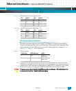
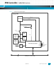
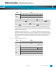
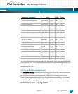
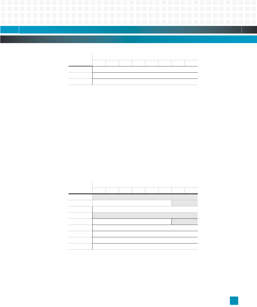
The first byte contains the responder’s Slave Address, rsSA. The second byte contains the
Network Function Code, netFn, and the responder’s Logical Unit Number, rsLUN. The third
byte contains the two’s-complement checksum for the first two bytes. The fourth byte con-
tains the requester’s Slave Address, rqSA. The fifth byte contains the requester’s Sequence
Number, rqSeq, and requester’s Logical Unit Number, rqLUN. The Sequence number may
be used to associate a specific response to a specific request. The sixth byte contains the
Command Number. The seventh byte and beyond contain parameters for specific com-
mands (if required). The final byte is the two’s-complement checksum of all of the message
data after the first checksum.
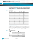
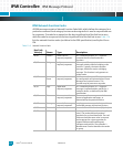
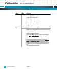
An IPMI response message (see
Table 11-5) is similar to a IPMI request message. The main
difference is that the seventh byte contains the Completion Code, and the eighth byte and
beyond hold data received from the controller (rather than data to send to the controller).
Also, the Slave Address and Logical Unit Number for the requester and responder are
swapped.
Table 11-5: Format for IPMI Response Message
6
Command
7:N
Data
N+1
Checksum
Byte: Bits:
7: 6: 5: 4: 3: 2: 1: 0:
1
rqSA
2
netFn rqLUN
3
Checksum
4
rsSA
5
rsSeq rsLUN
6
Command
7
Completion Code
8:N
Data
N+1
Checksum
Byte: Bits:
7: 6: 5: 4: 3: 2: 1: 0: