Monitor: Basic Operation
Katana®752i User’s Manual 10006024-04
15-4
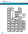
Figure 15-2: Power-up/Reset Sequence Flowchart
RESET
Initialize HID0
Initialize MSR
Relocate the base
of the MV64460
internal registers
750GX floating
point register
initialization
750GX BAT and
segment register
initialization
Invalidate the
cache
LED 0001
Invalidate and
enable the cache
Setup initial stack
and data region in
cache
Configure the
MV64460 device
chip selects for
flash and CPLD
Initialize the
MV64460 CPU
interface settings
Enable icache
Initialize the
PPCBoot
environment
Init. serial port per
baudrate
environment var.
LED 0101
Display version
string
Initialize
flash
Initialize malloc
area
Final Initialization
PCI &
cPCI (optional)
Is module a
Monarch
Enumerate PCI
per enumerate
environment
variable
Yes
Display board
serial number
No
Enable MV64460
interrupts
Configure dcache
per cachemode
and dcache
environment vars.
Configure icache
per icache
environment
variable
Configure L2
cache per l2cache
and l2mode
environment vars.
Display LED 1001
Initialize Ethernet
ports
Perform board
diagnostics per
powerondiags
environment var.
Turn off debug
LEDs and blink
front panel red
LED per blinked
environment var.
Main Loop
Check IPMI
controller per
ipmipresent
environment var.
Yes
No
Is cPCI
enabled?
Early I2C Init.
LED 0010
Early mem. Init.
(no ECC)
LED 0011
Early PCI &
cPCI Init
Stop Retries
Display CPU,
board, and bus
speed
LED 0110
Final I2C Init
Final mem. Init.
Clear per
clearmem & cfg.
per ecc env. vars.
LED 0111
Init. final stack
Re-locate
PPCBoot to RAM
LED 1000
Mini memory test
Display LED 0100


