Setup: Katana®752i Setup
10006024-04 Katana
®
752i User’s Manual
2-9
KATANA
®
752I SETUP
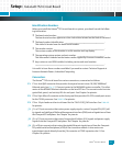
You need the following items to set up and check the operation of the Emerson
Katana
®
752i.
❐ Emerson Katana
®
752i board
❐ Card cage and power supply
❐ Serial interface cable (EIA-232)
❐ Terminal
Save the antistatic bag and box for future shipping or storage.
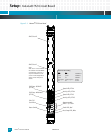
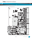
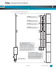
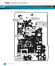
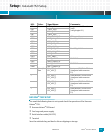
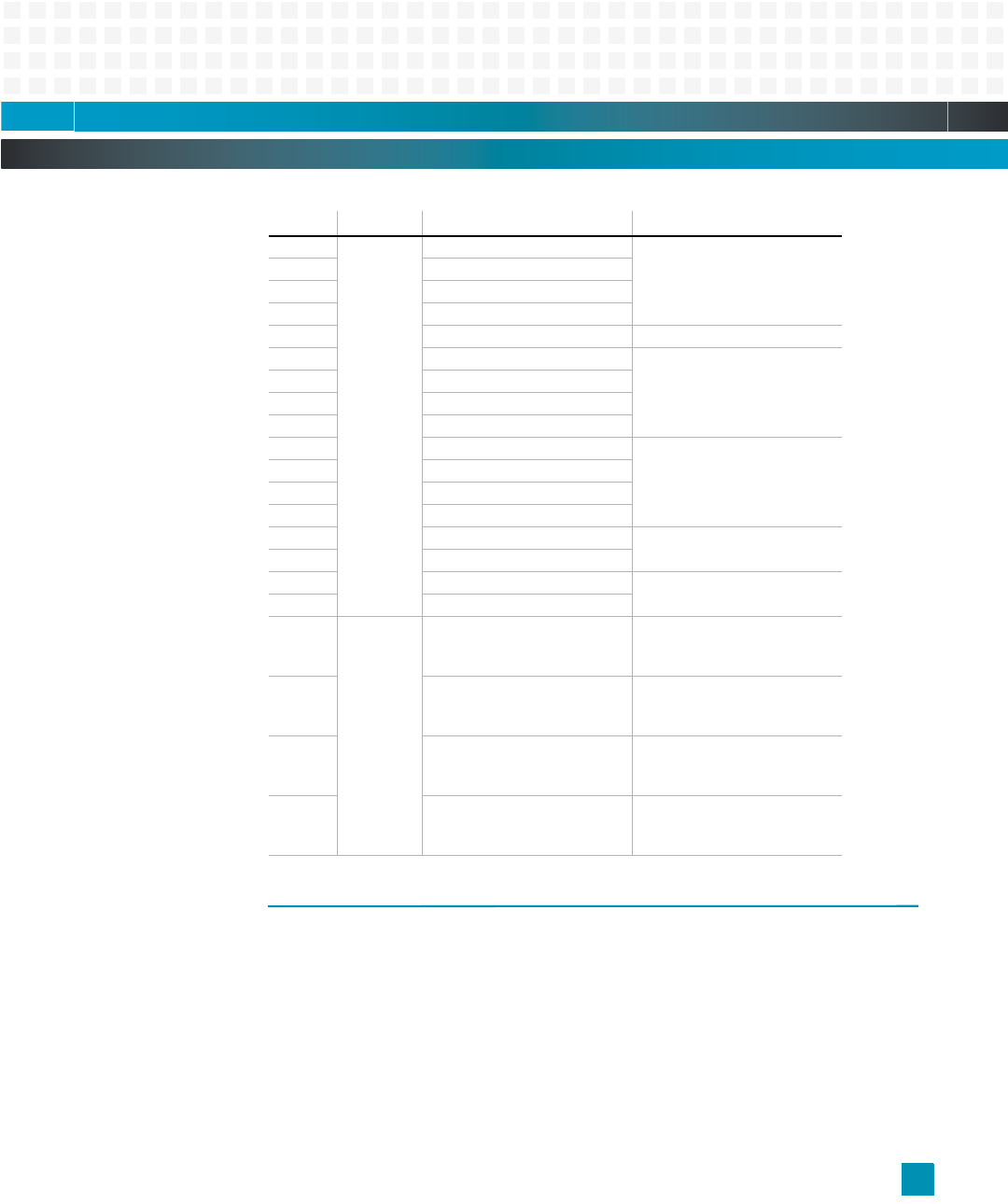
CR3 Green 750GL_LED4 programmable LED on front
panel
(via light pipe LP1)
CR4 750GL_LED3
CR5 750GL_LED2
CR6 750GL_LED1
CR10 IPMI_STATUSOUT IPMI controller status
CR32 GIG0_LINK_LED* Port 1 Gigabit Ethernet
CR33 GIG0_LINK2*
CR34 GIG0_ACT_LED*
CR35 GIG0_LINK1*
CR20 GIG1_ACT_LED* Port 2 Gigabit Ethernet
CR21 GIG1_LINK_LED*
CR22 GIG1_LINK2*
CR23 GIG1_LINK1*
CR39 PMC0_ACTLED PMC1 RMII
CR41 PMC0_LINKLED_R
CR38 PMC1_ACTLED PMC2 RMII
CR40 PMC1_LINKLED_R
– Green/Ye
llow
FP1_LED1_1
FP1_LED1_2
front panel SP LED for ETH4
(integrated with connector
P1)
–FP1_LED2_1
FP1_LED2_2
front panel ACT LED for ETH4
(integrated with connector
P1)
–FP2_LED1_1
FP2_LED1_2
front panel SP LED for ETH3
(integrated with connector
P1)
–FP2_LED2_1
FP2_LED2_2
front panel ACT LED for ETH3
(integrated with connector
P1)
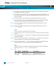
LED: Color: Signal Name: Comments:


