


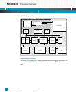
Processor: Processor Reset
Katana
®
752i User’s Manual 10006024-04
4-4
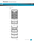
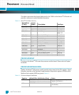
This table summarizes the physical addresses for the 750GL on the Katana
®
752i board and
provides a reference to more detailed information.
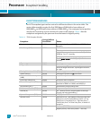
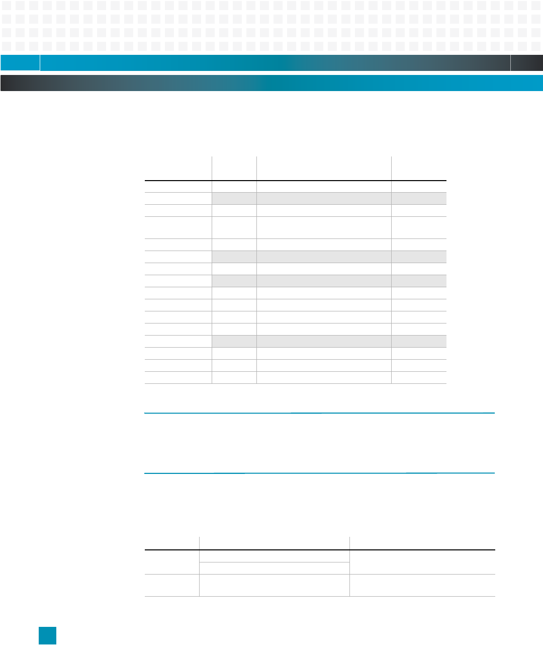
Table 4-2: Katana
®
752i Address Summary
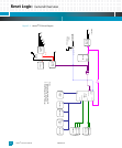
PROCESSOR RESET
Circuitry on the Katana
®
752i resets the processor and the board. Please refer to Chapter
for details.
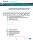
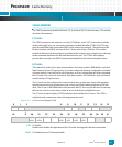
PROCESSOR INITIALIZATION
Initially, the Katana
®
752i powers up with specific values stored in the CPU registers. The ini-
tial power-up state of the Hardware Implementation Dependent registers (HID0) and the
Machine State register (MSR) are given in
Table 4-3.
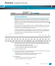
Table 4-3: CPU Internal Register Initialization
Hex Address
(32-bit):
Access
Mode: Description: See Page:
FF80,0000 R Boot Mirror
F834,0000
— Reserved –
F830,0000 R/W MV64460 SRAM page 5-1
F821,0000 R/W HSL PLD Registers page 4-1,
page 13-1
F820,0000 R/W Device Bus PLD Registers page 6-1
F811,0000
— Reserved –
F810,0000 R/W MV64460 Registers page 5-1
F808,0000
— Reserved –
F800,0000 R/W Flash socket page 5-7
E800,0000 R/W Flash (up to 128MB) page 5-7
E000,0000 R/W cPCI I/O Space page 5-4
C000,0000 R/W cPCI Memory Space page 5-4
B400,0000
— Reserved –
B000,0000 R/W PMC PCI I/O Space page 5-4
8000,0000 R/W PMC PCI Memory Space page 5-4
0000,0000 R/W SO-DIMM SDRAM (up to 2GB) page 5-7
Register: Default After Initialization (Hex): Notes:
HID0 8000,0000 (icache and dcache off) Hardware Implementation Dependent
register. (See Section )
8000,C000 (icache and dcache on)
MSR 0000,B032 Machine State register.
(See Section )