Katana
®
752i User’s Manual 10006024-04
iv
(blank page)
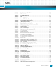
8Local PCI Bus
PCI Enumeration. . . . . . . . . . . . . . . . . . . . .8-1
PCI ID Select and Interrupts . . . . . . . . . . .8-1
Geographical Addressing . . . . . . . . . . . . .8-2
PCI Bus Control Signals . . . . . . . . . . . . . . .8-2
9 PTMC Interface
PTMC Installation . . . . . . . . . . . . . . . . . . . .9-1
PTMC Connector Pinouts . . . . . . . . . . . . .9-3
10Ethernet Interfaces
Ethernet Address . . . . . . . . . . . . . . . . . . 10-1
Ethernet Ports. . . . . . . . . . . . . . . . . . . . . 10-2
Front Panel Ethernet Connector Pinouts . . .
10-2
Optional RMII PHY Devices. . . . . . . . . . 10-3
11IPMI Controller
SMB/IPMI Overview . . . . . . . . . . . . . . . . 11-1
I/O Interface . . . . . . . . . . . . . . . . . . . . . . 11-4
I2C Interfaces . . . . . . . . . . . . . . . . . . . . . 11-5
IPMI Message Protocol . . . . . . . . . . . . . 11-6
IPMI Network Function Codes . . . .11-8
IPMI Completion Codes . . . . . . . . .11-9
Zircon PM IPMI Commands . . . . .11-10
Get Sensor Reading (Sensor/Event) . . .
11-11
Master Write-Read I2C (Application) . .
11-14
Write Setting (OEM) . . . . . . . . . . .11-15
Read Setting (OEM) . . . . . . . . . . . .11-16
Set Heartbeat (OEM) . . . . . . . . . . .11-17
Get Heartbeat (OEM). . . . . . . . . . .11-18
IPMI FRU Information . . . . . . . . . .11-19
IPMI Device SDR Repository. . . . .11-20
IPMI Event Messages . . . . . . . . . . .11-20
12Hot Swap
Hot Swap Logic (HSL) PLD. . . . . . . . . . . 12-1
cPCI Functionality. . . . . . . . . . . . . . . . . . 12-2
Hot Swap LED and Ejector Switch Control . .
12-2
cPCI Hot Swap. . . . . . . . . . . . . . . . . .12-2
Non-cPCI Hot Swap . . . . . . . . . . . . .12-4
Timing Considerations . . . . . . . . . . . . . 12-5
HEALTHY* Signal . . . . . . . . . . . . . . . . . . 12-6
13CT Bus Interface
PICMG 2.15 Configuration 2 . . . . . . . . 13-1
Katana®752i CT Bus Options. . . . . . . . 13-2
Clocking. . . . . . . . . . . . . . . . . . . . . . . . . . 13-2
Signal Control . . . . . . . . . . . . . . . . . . . . . 13-3
CT Bus Routing Without the T8110 (option
1). . . . . . . . . . . . . . . . . . . . . . . . . . . . . . . . . . . . 13-4
CT Bus Routing With the T8110 Installed
(option 2). . . . . . . . . . . . . . . . . . . . . . . . . . . . . 13-6
Local CT Bus Operation. . . . . . . . . . 13-7
H.110 CT Bus Operation. . . . . . . . . 13-8
14Backplane Signals
Overview . . . . . . . . . . . . . . . . . . . . . . . . . 14-1
Pinouts . . . . . . . . . . . . . . . . . . . . . . . . . . . 14-2
15Monitor
Command-Line Features. . . . . . . . . . . . 15-1
Basic Operation . . . . . . . . . . . . . . . . . . . 15-3
Power-Up/Reset Sequence . . . . . . 15-3
Power-Up Timing. . . . . . . . . . . . . . . 15-5
POST Diagnostic Results . . . . . . . . 15-6
Monitor SDRAM Usage. . . . . . . . . . 15-6
Monitor Recovery and Updates. . . . . . 15-7
Recovering the Monitor . . . . . . . . . 15-7
Updating the Monitor via TFTP . . . 15-7
Resetting Environment Variables . 15-8
Monitor Command Reference. . . . . . . 15-8
Command Syntax . . . . . . . . . . . . . . 15-8
Command Help . . . . . . . . . . . . . . . . 15-9
Typographic Conventions . . . . . . . 15-9
Boot Commands . . . . . . . . . . . . . . . . . . 15-9
bootbus. . . . . . . . . . . . . . . . . . . . . . . 15-9
bootcrc . . . . . . . . . . . . . . . . . . . . . .15-10
bootd. . . . . . . . . . . . . . . . . . . . . . . .15-10
bootelf. . . . . . . . . . . . . . . . . . . . . . .15-10
bootm . . . . . . . . . . . . . . . . . . . . . . .15-10
bootp. . . . . . . . . . . . . . . . . . . . . . . .15-10
bootv . . . . . . . . . . . . . . . . . . . . . . . .15-11
bootvx . . . . . . . . . . . . . . . . . . . . . . .15-11
rarpboot . . . . . . . . . . . . . . . . . . . . .15-11
tftpboot. . . . . . . . . . . . . . . . . . . . . .15-11


