


Backplane Signals: Pinouts
10006024-04 Katana
®
752i User’s Manual
14-5
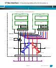
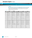
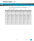
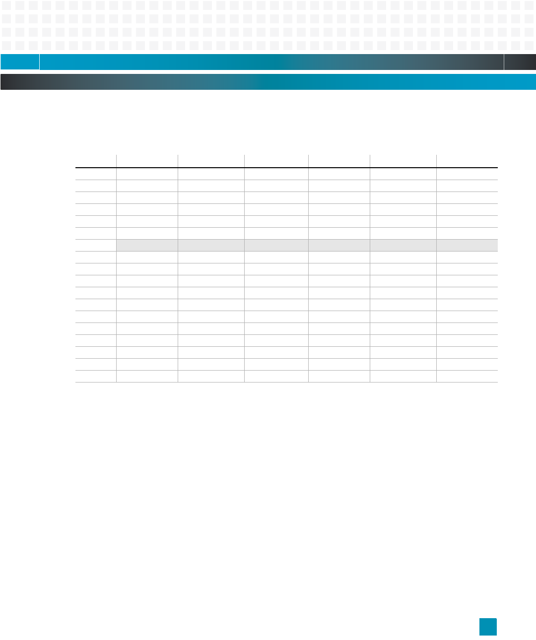
J4 is an optional 90-pin female connector (Emerson #01899070-00) that routes CT signals
between the PTMC sites and the cPCI backplane, as listed in the table below.
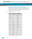
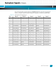
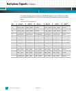
Table 14-4: cPSB Connector Pin Assignments, J4
Pin: Row A: Row B: Row C: Row D: Row E: Row F:
25 SGA4 SGA3 SGA2 SGA1 SGA 0 FRAME_GND5
24 J4_GA4 J4_GA3 J4_GA2 J4_GA1 J4_GA0 FRAME_GND4
23 EP_POS12 no connection CT_EN* EP_NEG12 no connection FRAME_GND3
22 PSF0* no connection no connection no connection no connection FRAME_GND2
21 no connection PSF1* no connection no connection no connection FRAME_GND1
20—15 no connection no connection no connection no connection no connection no connection
14—12
keying keying keying keying keying keying
11 CT_D29 CT_D30 CT_D31 LJ4_EPVIO CT_FA_R* ground
10 CT_D27 EP_3_3V CT_D28 LJ4_EP5V CT_FB_R* ground
9 CT_D24 CT_D25 CT_D26 ground FR_COMP* ground
8 CT_D21 CT_D22 CT_D23 LJ4_EP5V CT_C8A_R ground
7 CT_D19 EP_5V CT_D20 ground CT_C8B_R ground
6 CT_D16 CT_D17 CT_D18 ground CT_NETREF1 ground
5 CT_D13 CT_D14 CT_D15 LJ4_EP3_3V CT_NETREF2 ground
4 CT_D11 EP_5V CT_D12 LJ4_EP3_3V CT_SCLK ground
3 CT_D8 CT_D9 CT_D10 ground CT_SCLKx2* ground
2 CT_D4 CT_D5 CT_D6 CT_D7 ground ground
1 CT_D0 EP_3_3V CT_D1 CT_D2 CT_D3 ground