


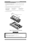
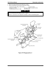
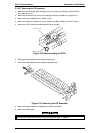
3.2.10.7 Removing the CR Assembly
1. Remove the rear/front edge guide assembly, front cover, paper eject assembly, rear/front tractor
unit , and printer cover.
2. Remove the panel board (see Section 3.2.2) and upper housing assemblies (see Section 3.2.7) .
3. Remove the printer mechanism (see Section 3.2.10 ).
4. Remove the left frame assembly (see Section 3.2.10.5) and RD assembly (see Section 3.2.10.6).
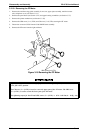
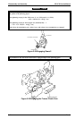
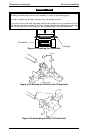
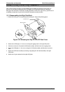
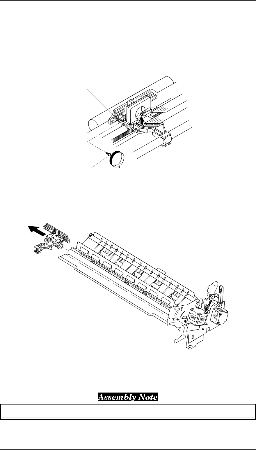
5. Disconnect 3 FFCs from the printhead and PW sensor assembly.
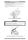
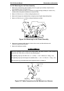
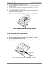
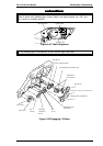
6. Disengage the timing belt from the CR motor pinion gear.
7. Remove the CR assembly from the rear/front CR guide shaft.
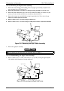
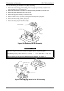
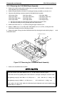
8. Remove the timing belt from the 2 holding slots under CR assembly.
9. Remove the CR assembly.
Adjust the platen gap and the bidirectional print alignment. Refer to Chapter 4.
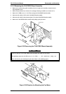
Figure 3-31 Removing the CR Assembly
PW Sensor Assembly
CB Screw (2 x 5 F/Zn)
Figure 3-30 Disconnecting the FFCs
FX-2170 Service Manual Disassembly and Assembly
Rev.A 3-21