


List of Figures
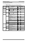
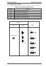
Figure 3-1. Screw Types and Abbreviations . . . . . . . . . . . . . . . . . . . . . . . . . . . . 3-3
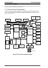
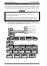
Figure 3-2. Flowchart for Disassembling the Printer . . . . . . . . . . . . . . . . . . . . . . 3-4
Figure 3-3. Before Starting Disassembly Procedures. . . . . . . . . . . . . . . . . . . . . 3-5
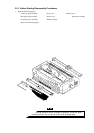
Figure 3-4. Removing the Panel Board Assembly . . . . . . . . . . . . . . . . . . . . . . . 3-6
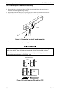
Figure 3-5. Lock Cover for CN1 and the FFC . . . . . . . . . . . . . . . . . . . . . . . . . . . 3-6
Figure 3-6. Removing the Printhead . . . . . . . . . . . . . . . . . . . . . . . . . . . . . . . . . . 3-7
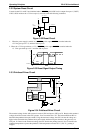
Figure 3-7. Connecting the Printhead FFCs . . . . . . . . . . . . . . . . . . . . . . . . . . . . 3-7
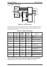
Figure 3-8. Removing the HP Sensor . . . . . . . . . . . . . . . . . . . . . . . . . . . . . . . . . 3-8
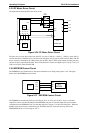
Figure 3-9. Removing the PW Sensor Assembly . . . . . . . . . . . . . . . . . . . . . . . . 3-8
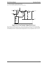
Figure 3-10. Mounting Position for the PW Sensor Assembly . . . . . . . . . . . . . . 3-9
Figure 3-11. Releasing the Locks for the Bushings . . . . . . . . . . . . . . . . . . . . . 3-10
Figure 3-12. Removing the Platen Assembly . . . . . . . . . . . . . . . . . . . . . . . . . . 3-10
Figure 3-13. Releasing the Upper Housing Assembly Hooks. . . . . . . . . . . . . . 3-11
Figure 3-14. Removing the Upper Housing Assembly . . . . . . . . . . . . . . . . . . . 3-11
Figure 3-15. Removing the Case Open Sensor Assembly . . . . . . . . . . . . . . . . 3-12
Figure 3-16. Removing the CR Motor Assembly. . . . . . . . . . . . . . . . . . . . . . . . 3-12
Figure 3-17. Removing the Printer Mechanism. . . . . . . . . . . . . . . . . . . . . . . . . 3-13
Figure 3-18. Removing the PF Motor . . . . . . . . . . . . . . . . . . . . . . . . . . . . . . . . 3-14
Figure 3-19. Removing the PG Sensor Assembly . . . . . . . . . . . . . . . . . . . . . . 3-15
Figure 3-20. Mounting the Cables for the PG Sensor Assembly . . . . . . . . . . . 3-15
Figure 3-21. Removing the Right Frame Assembly. . . . . . . . . . . . . . . . . . . . . . 3-16
Figure 3-22. Removing the Right Sub Frame . . . . . . . . . . . . . . . . . . . . . . . . . . 3-16
Figure 3-23. Engaging Gears 1 . . . . . . . . . . . . . . . . . . . . . . . . . . . . . . . . . . . . . 3-17
Figure 3-24. Engaging Gears 2 . . . . . . . . . . . . . . . . . . . . . . . . . . . . . . . . . . . . . 3-18
Figure 3-25. Engaging the Tractor Clutch Cam . . . . . . . . . . . . . . . . . . . . . . . . 3-18
Figure 3-26. Removing the Left Frame Assembly. . . . . . . . . . . . . . . . . . . . . . . 3-19
Figure 3-27. Cable Connection for the Release Lever Sensors . . . . . . . . . . . . 3-19
Figure 3-28. Removing the RD Assembly. . . . . . . . . . . . . . . . . . . . . . . . . . . . . 3-20
Figure 3-29. Engaging Gears for the RD Assembly . . . . . . . . . . . . . . . . . . . . . 3-20
Figure 3-30. Disconnecting the FFC . . . . . . . . . . . . . . . . . . . . . . . . . . . . . . . . . 3-21
Figure 3-31. Removing the CR Assembly. . . . . . . . . . . . . . . . . . . . . . . . . . . . . 3-21
Figure 3-32. Inserting the Timing Belt . . . . . . . . . . . . . . . . . . . . . . . . . . . . . . . . 3-22
Figure 3-33. Inserting the Oil Pad into the CR Assembly . . . . . . . . . . . . . . . . . 3-22
Figure 3-34. Assembling the Rear CR Guide Shaft . . . . . . . . . . . . . . . . . . . . . 3-22
Figure 3-35. Removing the Rear PE Sensor Assembly . . . . . . . . . . . . . . . . . . 3-23
Figure 3-36. Removing the Front PE Sensor Assembly . . . . . . . . . . . . . . . . . . 3-23
Figure 3-37. Removing the C166 MAIN Board Assembly. . . . . . . . . . . . . . . . . 3-24
Figure 3-38. Removing the C166 PSB/E Board Assembly . . . . . . . . . . . . . . . . 3-25
Figure 3-39. Direction for Mounting the Fan Motor . . . . . . . . . . . . . . . . . . . . . . 3-25
Figure 3-40. Releasing the Clips for the Right CSF Cover . . . . . . . . . . . . . . . . 3-26
Figure 3-41. Cable Alignment . . . . . . . . . . . . . . . . . . . . . . . . . . . . . . . . . . . . . . 3-27
Figure 3-42. Engaging 13 Gears . . . . . . . . . . . . . . . . . . . . . . . . . . . . . . . . . . . 3-27
Figure 3-43. Removing the E-ring . . . . . . . . . . . . . . . . . . . . . . . . . . . . . . . . . . . 3-28
Figure 3-44. Removing 1 Gear (29 mm) . . . . . . . . . . . . . . . . . . . . . . . . . . . . . . 3-28
Figure 3-45. Removing the CPB Tight Screw . . . . . . . . . . . . . . . . . . . . . . . . . . 3-28
Figure 3-46. Removing the Paper Support Block Assembly. . . . . . . . . . . . . . . 3-29
Figure 3-47. Removing the Paper Feed Roller Cover. . . . . . . . . . . . . . . . . . . . 3-29
Figure 3-48. Removing the Paper Eject Cover Assembly. . . . . . . . . . . . . . . . . 3-30
Figure 3-49. Assembling the Paper Eject Cover Assembly . . . . . . . . . . . . . . . 3-30