


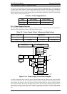
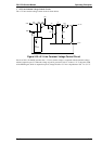
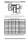


2.3.4 CR Motor Driver Circuit
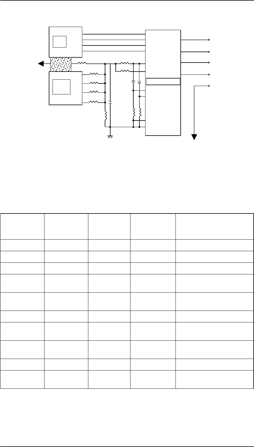
The CR motor driver circuit is shown below.
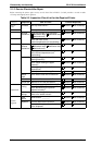
The carriage motor driver circuit controls the CR motor, using an open-loop, constant drive arrangement. 2-2
and 1-2 phases excite the motor. A 2-2 phase step is equivalent to a 1-2 phase step doubled. Ports 1 to 4 of
the SLA7024M are used to change the excitation phase, depending on the selected print mode. Table 2-8
describes the motor driver modes.
Table 2-8 CR Motor Driver Modes
Speed Mode
Print Speed
(CPS)
Drive
Frequency
(PPS)
Excitation
Phase
Applications
8/3 440 5280 2-2 Super Draft
2 330 3960 2-2 Draft
16/9 293.3 3520 2-2 Super Draft and Copy 2
50/33 250 6000 1-2
Bit image and head hot
mode
4/3 220 5280 1-2
Super Draft, Draft, Copy 2,
and Power down
1 165 3960 1-2 NLQ, Draft, and Power down
25/33 125 3000 1-2
NLQ, Super draft, Copy 2,
and Power down
2/3 110 2640 1-2
NLQ, Draft, Copy 2, and
Power down
1/2 82.5 1980 1-2 NLQ and Power down
1/4 41.3 990 1-2
NLQ, Copy 2, and Power
down
The SLA7024M (IC12) CR motor driver circuit detects and regulates the amount of current flowing in the
carriage motor coil. The current flowing through the coil varies, depending on the speed of the CR motor.
The CPU sets the amount of current via the Address /Data line. Signals are sent to ports 3 (RFA) and 14
(RFB) of the SLA7024M. The SLA7024M sets the coil current, depending on the CR speed.
CPU
CR A
CR-A
CR B
CR-B
Gate
Array
IN A
IN B
IN-B
6
5
17
16
IN-A
1
2
3
4
PG00
PG01
PG02
PG03
R73
R74
R75
R76
+5V
R72
C31
R68
R67
C29, 30
R71
R69, 70
RFA
RFB
RSA
RSB
GND A
GNB B
A
-A
B
-B
3
14
9
10
4
15
CRI0
CRI1
CRI2
CRI3
62
63
64
65
+35V
CRCOM
SLA7024M
Address
Data Line
Figure 2-35 CR Driver Circuit
FX-2170 Service Manual Operating Principles
Rev.A 2-25