


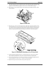
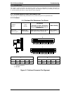
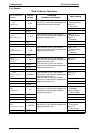
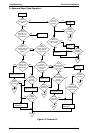
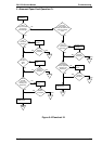
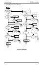
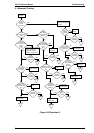

5.2.2 Sensors
Table 5-2 Sensor Test Points
Sensor Connector
Number
Test Pin
Number
Test Method
(Set Meter to DC Voltage. )
Meter Reading
CN4
(HP Sensor)
1: HP
Place one lead on pin 1 and the other
lead on pin 2, and check the voltage while
blocking the two sensor terminals.
Open:
+5 V
(Home position)
Short: 0 V
(Not home)
^
2: GND ^
^
3: +5 V ^
CN5
(Rear PE Sensor)
1: +5 V
Place one lead on pin 2 and the other
lead on pin 3, and check the voltage while
toggling the sensor lever.
Open: +5 V
(Paper loaded)
Short: 0 V
(No paper)
^
2: PE ^
^
3: GND ^
CN6
(Front PE Sensor)
1: PE
Place one lead on pin 1 and the other
lead on pin 2, and check the voltage while
toggling the sensor lever.
Open : +5 V
(Paper loaded)
Short: 0 V
(No paper)
^
2: GND ^
CN13
(PG Sensors
1 and 2)
1: PG 1
Place one lead on pin 1 and the other
lead on pin 2, and check the voltage while
toggling the sensor lever.
Place one lead on pin 3 and the other
lead on pin 4, and check the voltage while
toggling the sensor lever.
Open: +5 V
Short: 0 V
^
2: GND ^
^
3: PG 2 ^
^ 4: GND ^
CN12
(Release Sensors 1
and 2)
1: Release 1
Place one lead on pin 1 and the other
lead on pin 2, and check the voltage while
toggling the sensor lever.
Place one lead on pin 3 and the other
lead on pin 4, and check the voltage while
toggling the sensor lever.
Open: +5 V
Short: 0 V
^
2: GND ^
^
3: Release 2 ^
^
4: GND ^
CN7
(PW Sensor)
1: E
Place one lead on pin 1 and the other
lead on pin 2, and check the voltage while
inserting and removing paper between
the platen and sensor.
0 < Open Voltage
(No paper)
< Short Voltage
(Paper loaded)
^
2: GND ^
^
3: +5 V ^
^
4: A ^
CN2
(Case Open Sensor)
1: COPEN
Place one lead on pin 1 and the other
lead on pin 2, and check the voltage while
toggling the sensor lever.
Open: +5 V
(Case open)
Short: 0 V
(Case closed)
^
2: GND ^
Troubleshooting FX-2170 Service Manual
5-2 Rev. A