


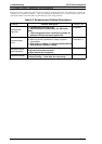
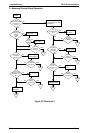
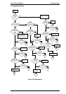
5.5 REPAIRING THE C166 MAIN BOARD ASSEMBLY
This section provides instructions to repair the C166 MAIN board assembly. It describes various problems,
symptoms, likely causes, and solutions. The checkpoint column provides proper waveforms, resistance
values, and other information for each component of C166 MAIN.
Note:
This information is necessary only for servicers who repair to the component level. Servicers who
repair to the unit level (including all servicers in the U.S.) can ignore this section.
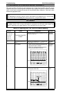
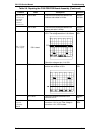
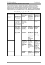
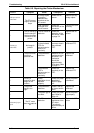
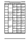
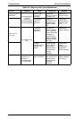
Table 5-7. Repairing the C166 MAIN Board Assembly
Problem
Cause Checkpoint Solution
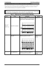
The printer
does not
operate at all.
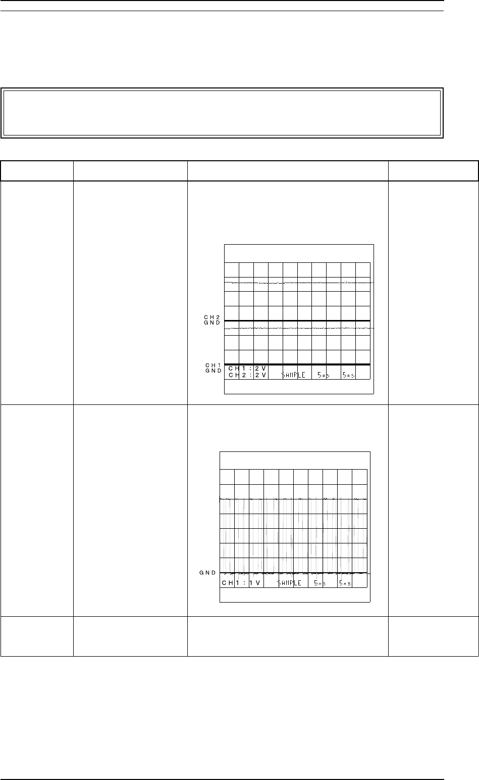
Reset IC10 is defective.
Check the voltage waveforms of the VCC
signal (CH1: IC10 pin 3 ) and VOUT signal
(CH2: IC10 pin 1) when power is turned
on.
Replace IC10.
^
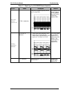
The PROM (IC3) is not
selected.
Check for a change in the signal from
HIGH/LOW at pin 137 of IC2.
Replace IC2 (or
replace the main
board).
The PSRAM (IC5) Check for a change in the signal from
HIGH/LOW at pin 132 of the IC.
Replace IC2 (or
replace the main
board).
Troubleshooting FX-2170 Service Manual
5-12 Rev. A