


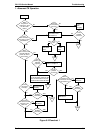
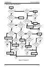
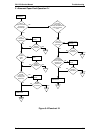
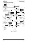
5.1 OVERVIEW
This chapter contains flowcharts and checkpoint tables to help you troubleshoot the printer. Flowcharts let
you isolate a faulty unit based on abnormal symptoms. The checkpoint tables let you identify the faulty part
or unit by checking the values or ranges listed for each component.
5.2 TROUBLESHOOTING INFORMATION
This section gives troubleshooting information to let you check test points for replaceable units.
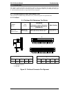
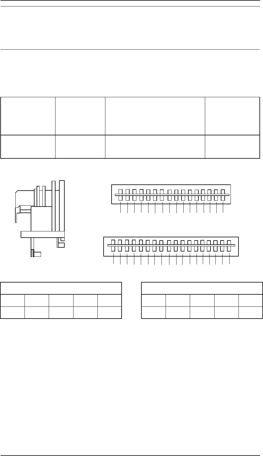
5.2.1 Printhead
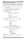
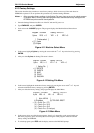
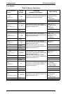
5-1. Printhead Coil Resistance Test Points
Common
Pin No.
Test
Pin No.
Test Method
(Set meter to ohms. Disconnect
the printhead after the printer is
powered off.)
Meter Reading
Refer to the
following figure.
Refer to the
following figure.
Place one lead on each pin and the
other lead on each common pin.
16.4 ±
10%
Ω
( at 25° C, 77° F)
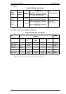
3
15
C5
2C6
5
16 11
C7
17
C8 14 4 8
1
913
7
C1
18 C2
12
C3
C4
610
TT
XX
X
X
XX
R
F
R
F
F
COM. C1 C2 C3 C4
1.7.13 9 10.18 6.12
R
COM. C5 C6 C7 C8
2.5.11 3.15 16.17 4.8.14
Pin No, Pin No,
T : Thermistor terminal
X : Not used
Figure 5-1 Printhead Connector Pin Alignment
FX-2170 Service Manual Troubleshooting
Rev.A 5-1