


1.3.2 Interface Specifications
This printer provides a bidirectional 8-bit parallel interface and a Type B optional interface slot, standard.
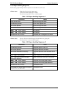
1.3.2.1 Parallel Interface (Forward Channel)
Transmission mode 8-bit parallel, IEEE-P1284, compatibility mode
Adaptable connector 57-30360 (Amphenol) or equivalent
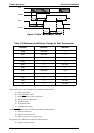
Synchronization
STROBE pulse
Handshaking BUSY and
ACKNLG signals
Signal level TTL compatible (IEEE-P1284 level 1 device)
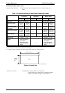
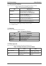
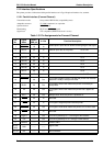
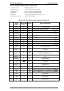
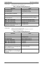
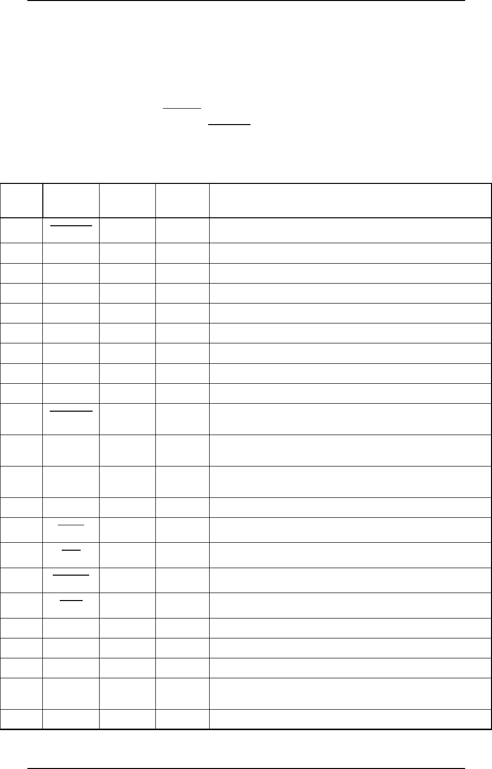
Table 1-31 Pin Assignments for Forward Channel
Pin
No.
Signal
Name
Return
GND pin
In /Out Function Description
1
STROBE 19 In
Strobe pulse. Input data is latched at falling edge of the signal
2 DATA1 20 In Parallel input data to the printer bit 0: LSB
3 DATA2 21 In bit 1
4 DATA3 22 In bit 2
5 DATA4 23 In bit 3
6 DATA5 24 In bit 4
7 DATA6 25 In bit 5
8 DATA7 26 In bit 6
9 DATA8 27 In bit 7: MSB
10
ACKNLG
28 Out
This signal (negative pulse) indicates the printer has received
data and is ready to accept more data.
11 BUSY 29 Out
This signal’s HIGH level means the printer is not ready to
accept data.
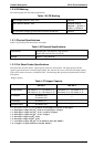
12 PE 28 Out
This signal’s HIGH level means the printer has a paper-out
error.
13 SLCT 28 Out Always HIGH when the printer is powered on.
14
AFXT 30 In
Not used.
31
INIT 30 In
This signal’s negative pulse initializes printer.
32
ERROR 29 Out
This signal’s LOW level means the printer is in an error state.
36
SLIN 30 In
Not used.
18 Logic H —— Out This line is pulled up to + 5 V through 3.3KΩ resistor.
35 +5V —— Out This line is pulled up to +5 V through 3.3KΩ resistor.
17 Chassis —— —— Chassis GND.
16, 33,
19-30
GND —— ——
Signal GND.
15, 34 NC —— —— Not connected.
FX-2170 Service Manual Product Description
Rev.A 1-21