


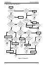
5.4 REPAIRING C166 PSB/PSE BOARD ASSEMBLY
This section provides instructions to repair a defective power supply board assembly. It describes various
symptoms, likely causes, and checkpoints. Checkpoints refer to proper waveforms, resistances, and other
values to check when evaluating the operation of any potentially faulty component. Check these values
and take the appropriate action.
Note:
This information is necessary only for servicers who repair to the component level. Servicers who
repair to the unit level (including all servicers in the U.S.) can ignore this section.
The
OPERATE
switch on the control panel only turns the secondary power circuit on or off, so
the primary circuit is live as long as the printer is connected to an AC power outlet. Before, you
repair or touch the power supply board, be sure to disconnect the AC power outlet.
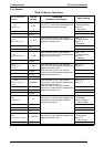
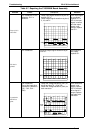
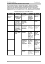
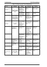
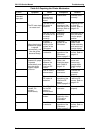
Table 5-6. Repairing the C166 PSB/PSE Board Assembly
Problem
Cause Checkpoint Solution
The 35 V and
5 V lines are
not output
when the
printer is
powered on.
The diode bridge DB1
is dead.
Measure the DC voltage between the pins
3 and 4 of the DB1.
Replace
the DB1.
^
The transformer coil is
open.
Measure the resistance of T1 transformer
coils at pins 12-15, 9-11, 7-8, 3-4.
Replace
the T1.
^
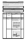
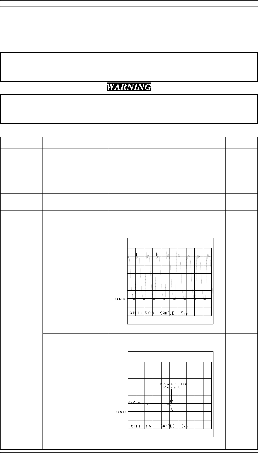
Q1 is dead. Check that the resistance between the
source and drain is infinite.
Check the voltage waveform between
the source and drain of the Q1.
Replace
the Q1.
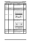
PC1 is dead. Check the voltage waveform between
pins 3 and 4 of the PC1.
Replace
PC1.
Troubleshooting FX-2170 Service Manual
5-10 Rev. A