


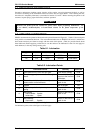
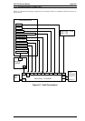


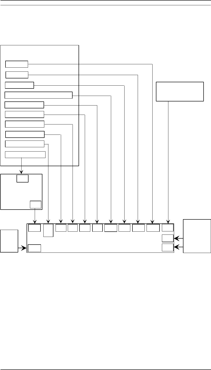
A.3 CONNECTOR SUMMARY
Figure A-1 illustrates how primary components are connected. Table A-1 summarizes functions and sizes of
the connectors.
Printer Mechanism
PG Sensor
Release Lever Position Sensor
PE- Rear Sensor
PE- Front Sensor
HP Sensor
PW Sensor
Printhead
Board Assy., C166 MAIN
CN13
CN5
CN6
CN4
Case Open Sensor
Board Assy., C166
PSB / PSE
CN3CN12
CN7
CN8
CN9
PF Motor
CR Motor
CN11 CN10
CN15
CN2
CN1
Board Assy.,
C165PNL
CN14
CSF
Bin 1
CN1
Host
Computer
Parallel I/F
CN2
Option I/F
Figure A-1. Cable Connections
FX-2170 Service Manual Appendix
Rev. A A-5