


3.2.10.6 Removing the Ribbon Drive (RD) Assembly
1. Remove the rear/front edge guide assembly, front cover, paper eject assembly, rear/front tractor
unit, and printer cover (see Section 3.2.1).
2. Remove the panel board (see Section 3.2.2) and upper housing assemblies (see Section 3.2.7).
3. Remove the printer mechanism (see Section 3.2.10).
4. Remove the left frame assembly (see Section 3.2.10.5).
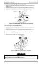
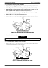
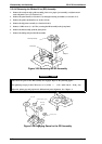
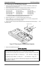
5. Remove 2 CBS screws (3 × 8, F/Zn ) securing the RD assembly to the front frame.
6. Remove the RD assembly from the front frame.
7. Remove the timing belt from the RD assembly.
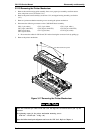
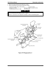
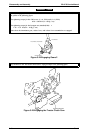
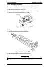
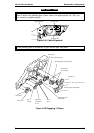
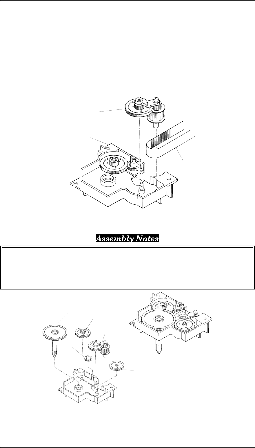
Notice how the gears in the RD assembly are engaged. Refer to the following figure.
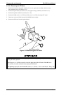
The tightening torque for the CBS screw (3 × 8, F/Zn) = 0.78 ~ 0.98 N.m (8 ~ 10 Kg - cm)
Adjust the platen gap and perform the bidirectional print alignment. See Chapter 4.
Driven Pully Assembly
RD Assembly
Timing Belt
Figure 3-28 Removing the RD Assembly
Rachet, RD
Combination Spring (7 g/ 23 g)
Spur Gear (25 mm)
Driven Pulley
Assembly
Spur Gear
(11 mm)
Figure 3-29 Engaging Gears for the RD Assembly
Disassembly and Assembly FX-2170 Service Manual
3-20 Rev.A