


3.3. Disassembly and Assembly of CSF Bin 1
This section describes procedures for disassembling and assembling the optional cut sheet feeder. In
general, you can install a component in the CSF simply by reversing the procedure for removing it.
Therefore, this section does not describe assembly procedures in most cases. If necessary, special notes on
assembling a component are given at the end of the description of each procedure.
3.3.1 Disassembling the Right Side Block
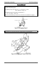
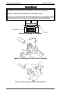
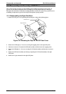
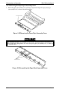
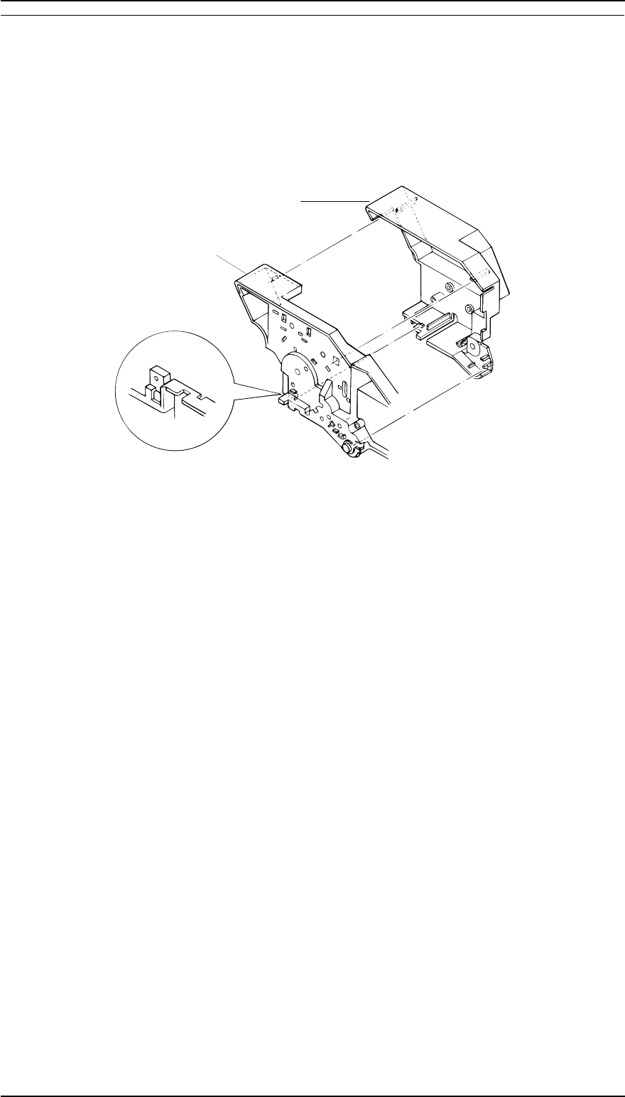
1. Remove the CSF gear cover by pushing and releasing the 4 clips in the following figure.
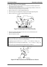
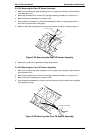
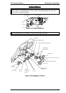
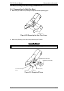
2. Remove the 3 CPB tight (3 × 12) screws securing the stepping motor to the right CSF frame.
3. Disconnect connector CN1 from the CSF board assembly, and then remove the stepping motor.
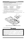
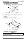
4. Remove the CPB tight (3 × 12) screw securing the CSF board assembly, and disconnect connector
CN2.
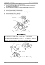
5. Remove the CSF board assembly by releasing 1 clip fixing the CSF board assembly to the right
CSF frame.
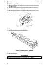
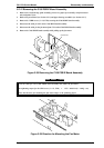
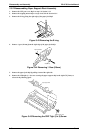
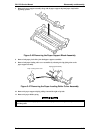
6. Remove the 13 gears mounted on the right CSF frame.
Right CSF Frame
CSF Gear Cover
Figure 3-40 Releasing the Clips for the CSF Gear Cover
Disassembly and Assembly FX-2170 Service Manual
3-26 Rev.A