


3.2.10.1 Removing the PF Motor
1. Remove the rear/front edge guide assembly, front cover, paper eject assembly, rear/front tractor
unit, and printer cover (see Section 3.2.1).
2. Remove the panel board (see Section 3.2.2) and upper housing assemblies (see Section 3.2.7).
3. Remove the printer mechanism (see Section 3.2.10).
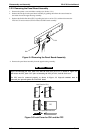
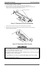
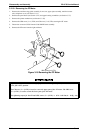
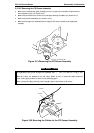
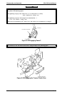
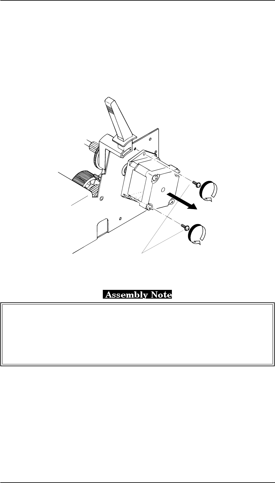
4. Remove the CBS screw (3 × 6, F/Zn) and CB screw (3 × 8, F/Zn) securing the PF motor.
5. Disconnect connector CN10 from the C166 MAIN board assembly.
6. Remove the PF motor from the right sub frame.
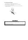
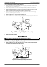
Before attaching the PF motor to the proper position on the right sub frame, set the release lever
to the full release position.
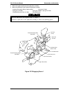
The CB screw (3 × 8, FZ/n) is used to secure the upper part of the PF motor. The CBS screw
(3 × 6, FZ/n ) is used to secure the lower part of the PF motor.
The tightening torque for the CB and CBS screws (3 × 8, F/Zn) = 0.78 ~ 0.98 Nm (8 ~ 10 Kg - cm)
CBS Screws (3 x 6 F/Zn)
Figure 3-18 Removing the PF Motor
Disassembly and Assembly FX-2170 Service Manual
3-14 Rev.A