


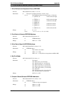
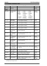
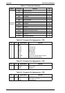

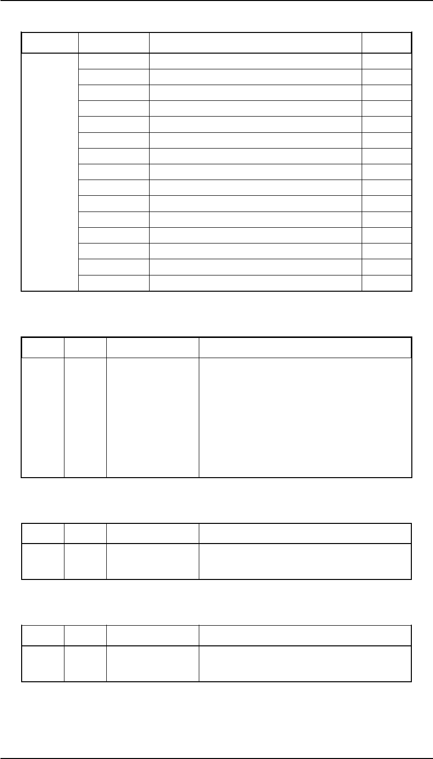
Table A-1. Connector Summary
Board Connector Function Pins
MAIN Board
Assembly
CN1 Parallel interface 36
CN2 Type B interface 36
CN3 C166 PSB/PSE board assembly 10
CN4 HP sensor 3
CN5 Rear PE sensor 3
CN6 Front PE sensor 2
CN7 PW sensor 4
CN8 Printhead 18
CN9 Printhead 16
CN10 PF motor 4
CN11 CR motor 5
CN12 Release lever position sensor 4
CN13 PG sensor 4
CN14 CSF bin 1 10
CN15 PNL board assembly 22
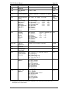
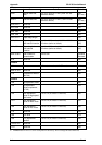
Table A-2. Connector Pin Assignments – CN3
Pin I/O Signal Name Function
1—-GP ——
2—-GP ——
3 I +35V +35 VDC line
4 I +35V +35 VDC line
5 —- GND Signal GND
6 —- GND Signal GND
7 I +5V +5 VDC line
8 I +5V +5 VDC line
9 I PWDN +35 V line overload detection signal
10 O PSC Power on/off switch signal
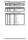
Table A-3. Connector Pin Assignments – CN4
Pin I/O Signal Name Function
1 I HP CR home position signal
2 —- GND Signal GND
3 — +5V +5 VDC
Table A-4. Connector Pin Assignments – CN5
Pin I/O Signal Name Function
1 —- +5V +5 VDC
2 I PE Rear paper end signal
3 — GND Signal ground
Appendix FX-2170 Service Manual
A-6 Rev.A