


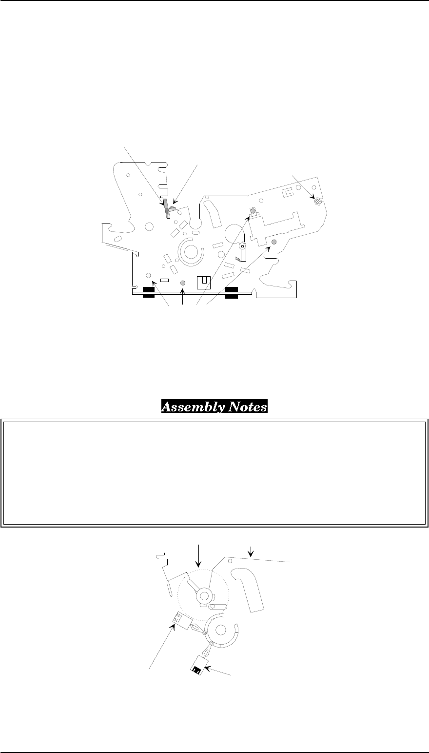
3.2.10.5 Removing the Left Frame Assembly
1. Remove the rear/front edge guide assembly, front cover, paper eject assembly, rear/front tractor
unit, and printer cover (see Section 3.2.1).
2. Remove the panel board assembly (see Section 3.2.2), upper housing assembly (see Section 3.2.7),
and then remove the printer mechanism (see Section 3.2.10 ).
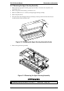
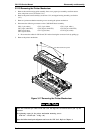
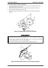
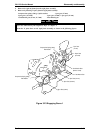
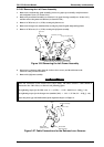
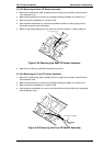
3. Remove 2 CBS screws (3 × 6, F/Zn) securing the platen cover.
4. Remove the hexagon nut (standard, M4) securing the front CR guide shaft and left frame.
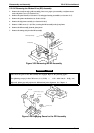
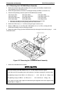
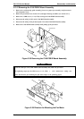
5 Remove 4 CBS screws (3 × 6, F/Zn) securing the left frame assembly.
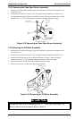
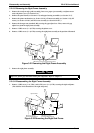
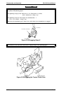
6. Disconnect 2 connector cables from the 2 release lever sensors, and then disconnect the
connector cable from the HP sensor.
7. Remove the left frame assembly.
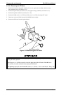
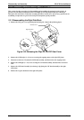
Notice the connection of the release lever sensor cables. The white conector’s cable should be
connected to the SW1 sensor, as shown in the following figure.
The tightening torque for the CBS screw (3 × 6, F/Zn) = 0.78 ~ 0.98 Nm (8 ~ 10 Kg f - cm)
The tightening torque for the hexagon nut (standard, M4) = 1.18 ~ 1.37 Nm (12 ~ 14 Kg f - cm)
Adjust the platen gap and bidirectional print alignment. Refer to Chapter 4.
CBS Screw (3 X 6 FZ/n ) Securing the Left Frame Assembly
Hexagon Nut (Normal, M4)
Platen Cover
C.B.S Screw (3 X 6 FZ/n)
Figure 3-26 Removing the Left Frame Assembly
Release SW1
(White connector)
Release SW2
(Black Connector)
Platen
Left Frame Assembly
Figure 3-27 Cable Connections for the Release Lever Sensors
FX-2170 Service Manual Disassembly and Assembly
Rev.A 3-19