


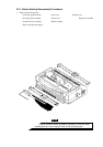
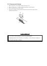
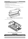
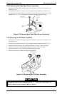
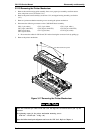
3.2.2. Removing the Panel Board Assembly
1. Remove the printer cover and ribbon cartridge (see Section 3.2.1).
2. Release the left clips for the panel board assembly by pushing them from the cutout located on
the inside front of the upper housing assembly.
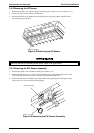
3. Release the flexible flat cable (FFC) by pulling the lock cover for CN1, and then disconnect the
FFC for CN1 and connector CN2 from the C165 PNL board assembly.
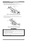
4. Remove the panel board assembly from the upper housing assembly.
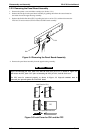
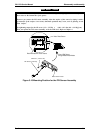
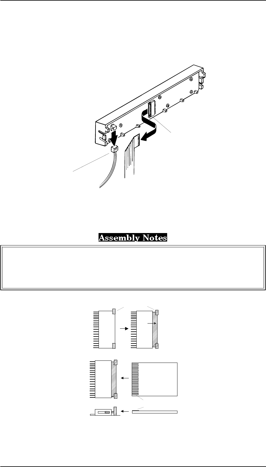
Before disconnecting the FFC from CN1, slide the lock cover for CN 1 as shown in Figure 3-5,
and release the FFC from CN1. After reconnecting the FFC for CN1, lock the lock cover .
The FFC must be connected properly, as shown in Figure 3-5. Exposed terminals must be
connected face upward against the C165 PNL board.
CN2
CN1
Figure 3-4 Removing the Panel Board Assembly
Lock Cover for CN 1
CN 1
FFC
Slide
Exposed terminals face
CN 1 CN 1
Figure 3-5 Lock Cover for CN1 and the FFC
Disassembly and Assembly FX-2170 Service Manual
3-6 Rev.A