


CHAPTER 3 Disassembly and Assembly
Table of Contents
3.1 OVERVIEW 3-1
3.1.1 Precautions. . . . . . . . . . . . . . . . . . . . . . . . . . . . . . . . . . . . . . . . . . . . . . . . . 3-1
3.1.2 Tools. . . . . . . . . . . . . . . . . . . . . . . . . . . . . . . . . . . . . . . . . . . . . . . . . . . . . . 3-1
3.1.3 Service Checks After Repair . . . . . . . . . . . . . . . . . . . . . . . . . . . . . . . . . . . 3-2
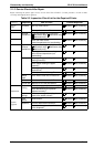
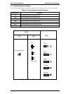
3.1.4 Specifications for Screws . . . . . . . . . . . . . . . . . . . . . . . . . . . . . . . . . . . . . . 3-3
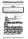
3.2 PRINTER DISASSEMBLY AND ASSEMBLY 3-4
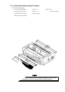
3.2.1 Before Starting Disassembly Procedures . . . . . . . . . . . . . . . . . . . . . . . . . 3-5
3.2.2 Removing the Panel Board Assembly . . . . . . . . . . . . . . . . . . . . . . . . . . . . 3-6
3.2.3 Removing the Printhead. . . . . . . . . . . . . . . . . . . . . . . . . . . . . . . . . . . . . . . 3-7
3.2.4 Removing the HP Sensor. . . . . . . . . . . . . . . . . . . . . . . . . . . . . . . . . . . . . . 3-8
3.2.5 Removing the PW Sensor Assembly . . . . . . . . . . . . . . . . . . . . . . . . . . . . . 3-8
3.2.6 Removing the Platen Assembly . . . . . . . . . . . . . . . . . . . . . . . . . . . . . . . . 3-10
3.2.7 Removing the Upper Housing Assembly . . . . . . . . . . . . . . . . . . . . . . . . . 3-11
3.2.8 Removing the Case Open Sensor Assembly, . . . . . . . . . . . . . . . . . . . . . 3-12
3.2.9 Removing the CR Motor Assembly . . . . . . . . . . . . . . . . . . . . . . . . . . . . . 3-12
3.2.10 Removing the Printer Mechanism . . . . . . . . . . . . . . . . . . . . . . . . . . . . . 3-13
3.2.10.1 Removing the PF Motor Assembly . . . . . . . . . . . . . . . . . . . . . . . 3-14
3.2.10.2 Removing the PG Sensor Assembly . . . . . . . . . . . . . . . . . . . . . 3-15
3.2.10.3 Removing the Right Frame Assembly . . . . . . . . . . . . . . . . . . . . 3-16
3.2.10.4 Disassembling the Right Frame Assembly. . . . . . . . . . . . . . . . . 3-16
3.2.10.5 Removing the Left Frame Assembly . . . . . . . . . . . . . . . . . . . . . 3-19
3.2.10.6 Removing the Ribbon Drive (RD) Assembly . . . . . . . . . . . . . . . 3-20
3.2.10.7 Removing the CR Assembly. . . . . . . . . . . . . . . . . . . . . . . . . . . . 3-21
3.2.10.8 Removing the Rear PE Sensor Assembly . . . . . . . . . . . . . . . . . 3-23
3.2.10.9 Removing the Front PE Sensor Assembly . . . . . . . . . . . . . . . . . 3-23
3.2.11 Removing the C166 MAIN Board Assembly . . . . . . . . . . . . . . . . . . . . . . 3-24
3.2.12 Removing the C166 PSB/E Board Assembly . . . . . . . . . . . . . . . . . . . . . 3-25
3.3 DISASSEMBLY AND ASSEMBLY OF CSF BIN 1 3-26
3.3.1 Disassembling the Right Side Block . . . . . . . . . . . . . . . . . . . . . . . . . . . . . 3-26
3.3.2 Disassembling the Paper Support Block Assembly . . . . . . . . . . . . . . . . . 3-28
3.3.3 Removing the Paper Eject Cover Assembly . . . . . . . . . . . . . . . . . . . . . . 3-30
3.4 DISASSEMBLY AND ASSEMBLY OF CSF BIN 2 3-31
3.4.1 Disassembly Right Side Block. . . . . . . . . . . . . . . . . . . . . . . . . . . . . . . . . . 3-31
3.4.2 Disassembly Paper Support Block Assembly . . . . . . . . . . . . . . . . . . . . . . 3-32