


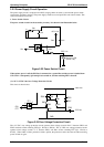
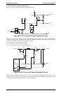
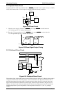
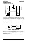
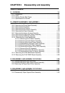


2.3.2 System Reset Circuit
Control circuits IC1 and IC2 are initialized when a RESET signal (LOW level) is output from port 1 (VOUT)
of IC10. IC10 monitors the +5 V line on port 3, and resets under the following conditions:
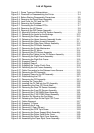
1. When the power supply is turned on, a
RESET signal is output. RESET is canceled when the
+5 V line goes up to 4.2 V, and then 100 ms passes.
2. When the +5 V line goes below +4.2 V, a
RESET signal is output. RESET is canceled when the
+5 V line goes back up to 4.2 V and then 100 ms passes.
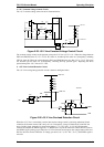
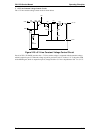
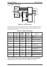
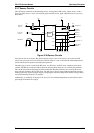
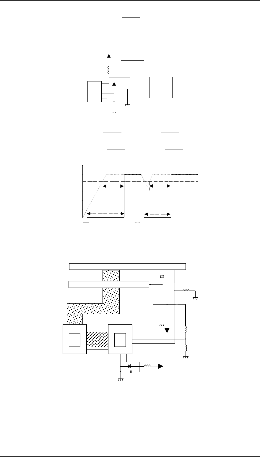
2.3.3 Printhead Driver Circuit
The standard voltage for the A/D converter is made in ZD1 and input to CPU port 78. Based on this standard
voltage, the A/D converter in the CPU operates. Port 74 monitors the +35 V line between R50 and R51 to
determine the printhead drive pulse width. Using the monitored voltage, the CPU converts the voltage to a
digital value and decides the printhead drive pulse width, and then transports the data to the gate array via
CPU port 19. Based on the monitored voltage, the CPU decides the printing interval. Port 73 monitors the
printhead temperature to protect the printhead. If the temperature exceeds 107° C (225° F) , printing is
stopped.
CPU
Gate
Array
C19
ZD1
+35V
7879
74
73
R51
R50
+35V
R49
Address
Data Line
37
44
~
28
~
21
Printhead Drive Signal
69 76~89 91~93
Printhead Drive Transistor Q5~Q13, Q14~22
Print Head
HTMP
+
C9
+35V +35V
32
19
Figure 2-34 Printhead Driver Circuit
VOUT
MRES
VCC
GND
+5V
+5V
R47
1K
IC10
PST5920
C16
0.1U
IC1
IC2
E05813YA
TPM96C041AF
23 RESET
61
RESET
1
2
3
4
Figure 2-32 Reset Circuit
1
2
3
4
5
VCC (+5V line)
VOUT (RESET)
RESET
RESET
Power On
(v)
100ms
100ms
Figure 2-33 Reset Signal Output Timing
Operating Principles FX-2170 Service Manual
2-24 Rev.A