


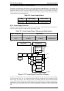
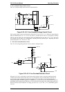
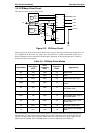
3. +35 V Constant Voltage Control Circuit
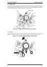
The +35 V constant voltage control circuit is illustrated below.
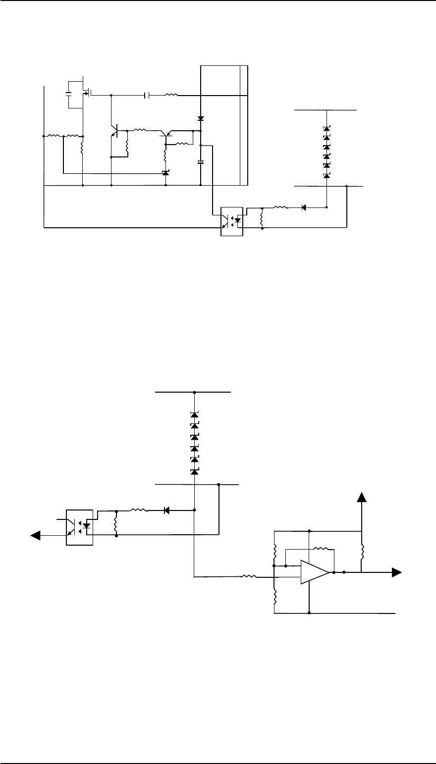
The constant voltage control circuit operates to keep the 35 V line at 35 V ± 6 %. When the voltage between
ZD51 and ZD85 becomes 32.7 V ± 2.75 %, PC1 turns on, and then Q2 also turns on. Consequently, switching
FET Q1 shuts off. When the voltage between ZD51 and ZD85 becomes less than 32.7 ± 2.75 V, PC1 turns
off, and then Q2 also turns off. Consequently, switching FET Q1 operates again. Repeating the above
operation keeps the +35 V line at 35 V ± 6%.
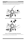
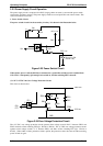
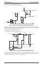
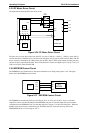
4. +35V Line Overload Detection Circuit
The +35 V line voltage drop protection circuit is shown in the figure below.
When the +35 V line is overloaded, it means that constant voltage control is not being maintained. In this
condition, the forward current of PC1 drops to 0 A. Consequently, voltage Vf between PC1 and D81 also
drops. On this circuit, when the Vf voltage drops below 1.3 V (+35 V line: 33.1 V), IC528 detects the
overload and outputs the PWDN signal (+5 V: HIGH active) to port 20 of the CPU. When the CPU receives
this PWDN signal, printing stops. When the +35 V line becomes normal again, the voltage between PC1 and
D81 also becomes normal. When the Vf voltage goes above 1.6 V (+35 V line: 33.4 V), the PWDN signal is
removed.
+35V Line
ZD81
ZD51
ZD82
ZD83
ZD84
ZD85
D81
R56
R57
GND Line
9+
10+
11
R11C13
Q3
R14
C12
+
Q1
1
2
8
7
R20 R21
R19
C15
Q2
R13
R15
R16
IC1
Figure 2-25 +35 V Line Constant Voltage Control Circuit
+35V Line
ZD81
ZD51
ZD82
ZD83
ZD84
ZD85
D81
R56
R57
GND Line
1
2
8
7
PWDN
+5V Line
GND
R87
R86
R83
R84
+
-
7
8
4
6
5
PC1
Q31
R20
Figure 2-26 +35 V Line Overload Detection Circuit
FX-2170 Service Manual Operating Principles
Rev.A 2-19