


3.2.11 Removing the C166 MAIN Board Assembly
1. Remove the rear/front edge guide assembly, front cover, paper eject assembly, rear/front tractor
unit, and printer cover (see Section 3.2.1)
2. Remove the panel board (see Section 3.2.2) and upper housing assemblies (see Section 3.2.7).
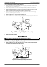
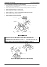
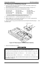
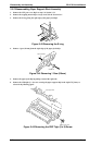
3. Disconnect the following connectors from the C166 MAIN board assembly.
CN3 (10-pin , blue) CN4 (3-pin, white) CN5 (3-pin, black)
CN6 (2-pin, white) CN7 (4-pin, white FFC) CN8 (18-pin, white FFC)
CN9 (16-pin, white FFC) CN10 (4-pin, blue) CN11 (5-pin, blue)
CN12 (4-pin, white) CN13 (4-pin, black) CN15 (22-pin FFC)
❇ Disconnect the cables for CN10 and CN11 after releasing the connector lock.
❇ Disconnect the cable for CN3 by pushing down the connector lock.
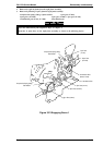
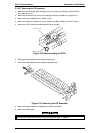
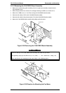
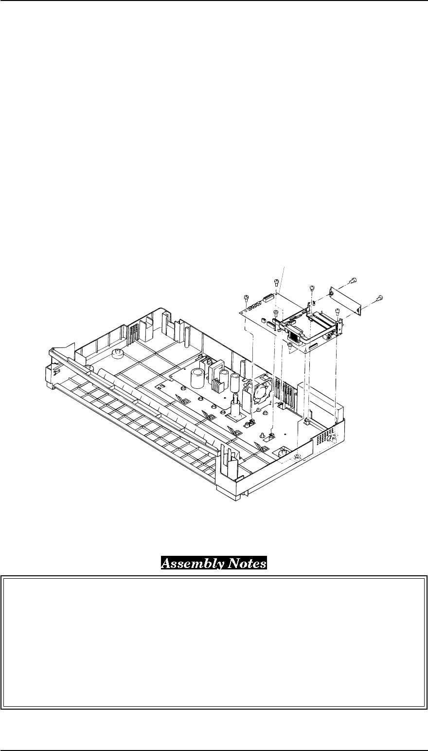
4. Remove the 2 CBS screws ( 3 × 12, F/Zn) securing the upper connector cover.
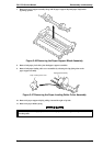
5. Remove 5 CBB screws (3 × 12, F/Zn) and 1 CBC lamitate screw (3 × 8, F/Zn ) securing the C166
MAIN board assembly to the lower housing assembly.
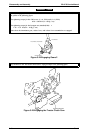
6. Remove the option I/F cage from the C166 MAIN board by releasing the hooks which is fixing it to the
C166 MAIN board.
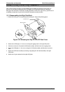
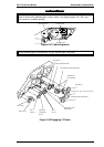
7. Remove the C166 MAIN board assembly.
Notice the location of the CBC lamitite screw (3 × 8, F/Zn). Refer to the above figure.
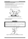
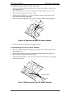
Lock CN10 and CN11 by pushing down each connector’s lock after inserting the connector cable.
The tightening torque for the CBB (3 × 12, F/Zn) screw = 0.78 ~ 0.98 Nm (8 ~ 10 Kg f - cm)
The tightening torque for CBB (3 × 8, F/Zn) screw = 0.78 ~ 0.98 Nm (8 ~ 10 Kg f - cm)
If you replace the main board, adjust the bidirectional print alignment and run the default setting
program. Refer to Chapter 4.
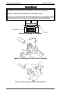
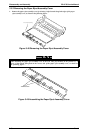
C 166 MAIN Baord Assembly
Figure 3-37 Removing the C166 MAIN Baord Assembly
Disassembly and Assembly FX-2170 Service Manual
3-24 Rev.A