


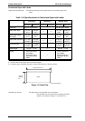
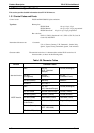
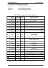
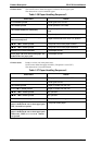
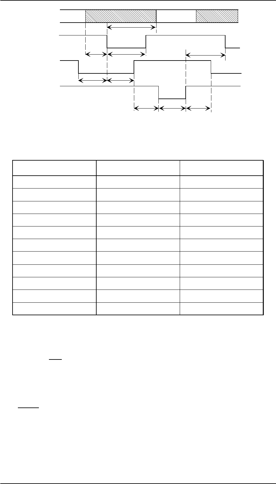
Table 1-32 Maximum and Minimum Timings for Data Transmission
Parameter Minimum Maximum
setup 500 nsec ——-
thold 500 nsec ——-
t stb 500 nsec ——-
tready 0 ——-
tbusy —— 500 nsec
treply —— ——-
tack 500 nsec
10 µs
tnbusy 0 ——-
tnext 0 ——-
ttout —— 120 nsec
ttin —— 200 nsec
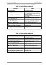
❒ The BUSY signal is active (HIGH level) under the conditions below:
❒ During data receipt.
❒ If the input buffer is full.
❒ If the
INIT signal is active (LOW level).
❒ During hardware initialization.
❒ In self-test mode.
❒ In adjustment mode.
❒ In default-setting mode.
❒ The
ERROR signal is active (LOW level) under the conditions below:
❒ If there is a fatal error.
❒ If there is a paper-out error.
❒ If the cover is open (cover open error).
PE signal is active (HIGH level) under the conditions below:
❒ If there is a paper-out error.
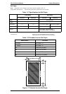
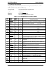
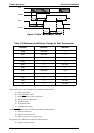
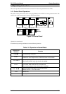
data byte n
data byte n+1
t
hold
t
setup
t
stb
t
next
t
ready
t
busy
t
reply t
ack
t
nbusy
DATA
STROBE
BUSY
ACKNLG
Figure 1-8 Data Transmission Timing
Product Description FX-2170 Service Manual
1-22 Rev.A