


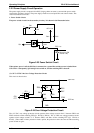
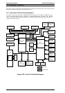
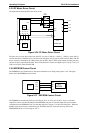


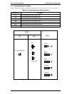
2.3.5 PF Motor Driver Circuit
The figure below shows the PF motor driver circuit.
The gate array receives phase data from the CPU via ports 5 (PG10), 6 (PG11), 7 (PG12), and 8 (PG13),
converts the data to UDN2917 form, and then sends that phase data to ports 43 (PH1) and 26 (PH2). The PF
driver current is controlled by the 74LS32 using port 68 (PF1) and 67 (PF2) signals output from the gate array
and port 61 (P27) output from the CPU. These controlled drive currents are output to ports 2 (I10), 1 (I11), 23
(I20), and 24 (I21) of the UDN2917EB.
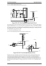
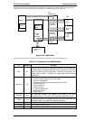
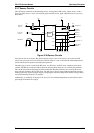
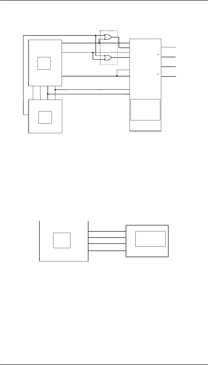
2.3.6 EEPROM Control Circuit
The EEPROM is non-volatile memory that stores information even if the printer power is off. The figure
below shows the EEPROM control circuit.
The EEPROM is controlled by CPU ports 9 (P70), 10 (P71), 11 (P72), and 12 (P73). Port 11 is the data
output line used to save the information to the EEPROM, and port 12 is the data input line used to read the
saved data from the EEPROM. Port 70 is the chip select line, and port 71 is the clock timing line. When the
PWDN signal (power down) is detected on port 20 (INTO), the CPU writes the necessary data to the
EEPROM before the +5 V line drops to 4.75 V.
Gate
Array
CPU
PH1
PH2
PP
G0
PP
G1
10
9
43
26
I10
I11
P27
61
IC6
I20
PFI2
PFI1
I21
3
1
2
6
5
4
PF A
PF-A
PF B
PF-B
1
2
3
4
PP
G3
PP
G2
8
7
PG
10
PG
11
PG
12
PG
13
UDN2917EB
VREF2
42
27
VREF1
HOLD
66
67
68
74LS32
5
67
8
IC11
6
3
18
21
A
A
B
B
Figure 2-36 PF Motor Driver Circuit
CPU
P70
P71
P72
P73
CS
CK
DI
DO
EEPROM
9
10
11
12
1
2
3
4
IC 8
Figure 2-37 EEPROM Control Circuit
Operating Principles FX-2170 Service Manual
2-26 Rev.A