


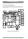
2.2.2 Power Supply Circuit Operation
The power supply circuit is composed of an RCC (ringing choke converter) system and the power switch
circuit in the secondary circuitry. The power supply circuit has several protection and control circuits. This
section describes these circuits.
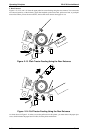
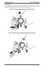
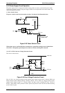
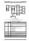
1. Power Switch Circuit
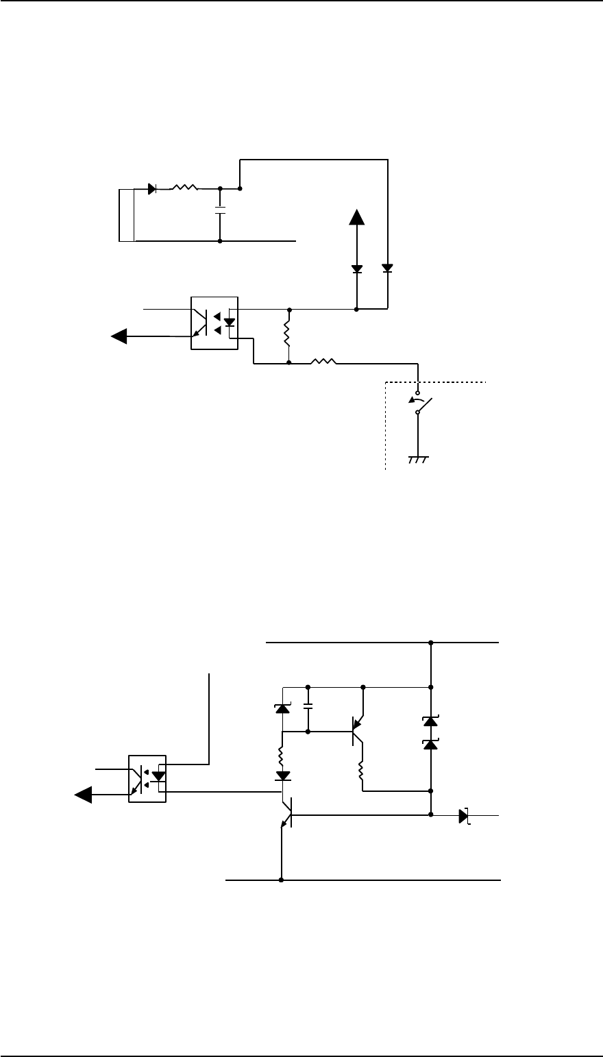
The power switch circuit is in the secondary circuitry. It is shown in the illustration below.
When printer power is off, the PSC line is connected to a ground line and the current is loaded from
C55 to PC1. Consequently, Q32 and Q31 are turned on, and the switching FET is shut off.
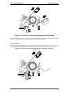
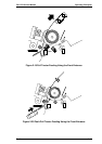
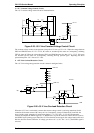
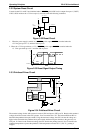
(2) +35 V/+5 VDC Line Over Voltage Protection Circuit
This circuit is shown below.
The +35 VDC over voltage protection circuit operates when voltage exceeds 42.42 V between ZD52 and
ZD87 and shuts off the switching FET (Q1: K2126 or K2130). The +5 VDC over voltage protection circuit
operates when voltage exceeds 7.5 V between ZD53, and shuts off the switching FET (Q1: K2126 or
K2130). When either of these protection circuits operate, the protection cannot be removed without turning
power off and on again.
D85
D84
R68
R69
3
4
6
5
Q31
Operation SW
(Power SW)
PSC line
OFF
+35V Line
C55
R91
D52
8
7
PC1
Figure 2-23 Power Switch Circuit
ZD52
ZD87
+35V Line
R90
C82
Q81
Q55
D82
R89
ZD86
ZD53
+5V Line
GND
Q31
FET
PC1
3
4
6
5
Figure 2-24 Over Voltage Protection Circuit
Operating Principles FX-2170 Service Manual
2-18 Rev.A